I am not sure this has been sufficiently answered.
I don't have an answer per-se, but I can share what I've learned in search of an answer:
The best, given answer- and really the only actual answer is the quote by way of @quack quixote from Wikipedia.
Each voltage transmits through three pins ganged together because the small contacts by themselves cannot supply sufficient current for some devices. (Each pin should be able to provide 1.5 A.)
But why 3 of each. They can't be used for signaling, you can't pull one V+ low, or pull a ground-up because it's serially connected. Why not make a larger contact and use just one, If you look, each power pin is immediately adjacent to its friends-
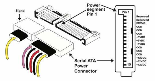
12V-12V-12V-Gnd-Gnd-Gnd-5V-5V-5V-Gnd-Gnd-Gnd-3.3-3.3-3.3
So, why not remove the spacing and make a larger contact area, if needed. Ta-Da! Now the connector is 1/2 as wide. 12V-Gnd-5V-Gnd-3.3 (Or 2/3rds more precisely). In most cases, it's not redundant either, it isn't broken out to 3 until the adapter.
Interesting point 1-
That 3.3v line is apparently 3.3 no longer- at least for 2 of 3...
To sum up, for products supporting the optional SATA 3.3 power disable (PWDIS) function, the third pin (P3) of the SATA connector is now assigned as the Power Disable Control pin. If P3 is driven HIGH (2.1V-3.6V), the power to the drive circuitry will be cut. All drives with this optional feature will not power up if a legacy SATA connector is used. This is because P3 driven HIGH will prevent the drive from powering up. The easy, and not so elegant, solution is to use a 4-pin Molex to SATA connector or a power supply equipped with SATA connectors that follow the SATA 3.3 specification.
Source-Toms Hardware
Western Digital Whitepaper
But wait, there's more-
In addition, according to the SATA-IO Standards group, the 11th pin (the second ground from left in my written version.) provides staggered spinup AND an activity indicator- presumably for flashing LEDs and such.
From a SATA-IO Press Release (SATA-IO is the International Organization that owns and manages Serial ATA specifications as open industry standards.):
Additional advancements in the revision 3.3 specification include:
• Power Disable: Allows for remote power cycling of SATA drives to help ease maintenance in the
data center.
• Single-Pin Activity Indicator and Spin-Up Control: An activity indicator and staggered spin-up
can be controlled by the same pin, adding flexibility and providing users with more choices.
• Transmitter Emphasis Specification: A new transmitter specification increases interoperability
and reliability in electrically demanding environments.
SATA-IO Press Release
You would think the answer would be found, in depth on the SATA-IO website, but I have been unable to find it. Much of it is behind a paywall, unfortunately. Perhaps someone with this arcane answer can provide more info as to the thought process behind it. It would be in the 1.0 specifications I imagine.
A discussion on the arrangement:
...from a once rival, now sister site:
A closely related discussion also has some excellent ideas, if they aren't sufficiently cited. Wikipedia perhaps...?
The new SATA power connector contains many more pins for several reasons:
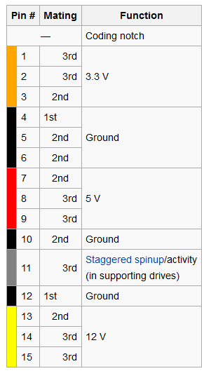
3.3 V is supplied along with the traditional 5 V and 12 V supplies. To reduce impedance and increase current capability, each voltage is supplied by three pins in parallel, though one pin in each group is intended for precharging.
Five parallel pins provide a low-impedance ground connection.**
Two ground pins, and one pin for each supplied voltage, support hot-plug precharging. Ground pins 4 and 12 in a hot-swap cable are the longest, so they make contact first when the connectors are mated. Drive power connector pins 3, 7, and 13 are longer than the others, so they make contact next. The drive uses them to charge its internal bypass capacitors through current-limiting resistances. Finally, the remaining power pins make contact, bypassing the resistances and providing a low-impedance source of each voltage.
This two-step mating process avoids glitches to other loads and possible arcing or erosion of the SATA power connector contacts.
Pin 11 can function for staggered spinup, activity indication, both, or nothing.
Here are the pins, as a reference for above:
**This explains some other interesting aspects, though I am unsure what they mean by 5 parallel pins. 5 parallel grounds I suppose (6- pin 11).
Conclusion
In conclusion, the only reasonable assumption is that these additional pins were left, in some cases, to provide additional functionality in the future. And perhaps its the idea of a better connection, through redundancy maybe. It seems in 2 places, its been stated that the parallel connections are preferred. This I guess ensures that at least one of the pins are making contact, to combat corrosion and other effects. When these pins contact a surface, the actual contact area is relatively small, this was perhaps a way to improve that. However, this is not the case for data, but perhaps its less of an issue. I notice that one particular pin of my iPhone connector always collects black grime, while the remainder are unmarred. I think this shows the corrosion that can build up on particular power pins.


They should have given us two power connectors: one for a limited current 5V and 12V (total of 4 pins, with a separate ground for each), and a separate one for all the server/enterprise extras like 3v3, staggered spin-up, more current, etc. 99.9% of all HDDs would come with a tiny 4 pin power connector only and nothing else. Alas. – RomanSt – 2015-06-05T14:20:40.540
...and yet all of the power adapters I see don't handle the 3.3v pin. It must be considered de facto optional. – Broam – 2010-03-23T14:04:38.870
@Broam: there's 3x 3.3v pins. are they all missing? they might be (should be) missing on molex-to-SATA power adapters; those won't have a 3.3v lead, just 5v/12v – quack quixote – 2010-03-23T16:56:23.693
1I was referring to the Molex(TM) adapters, yes. The only ones I see that handle 3.3v come straight from a PSU. – Broam – 2010-03-23T17:53:14.523
@Broam: yep. you'd need additional hardware to provide 3.3v from a 5v & 12v source. for most of what you'd need the molex adapters for (SATA optical drives or hard drives for an older computer), the devices can get away with not using the 3.3v. newer low-power devices may not work properly with those power plugs. – quack quixote – 2010-03-23T18:55:15.347
3.3v isn't really a requirement yet I have only seen it on a 1.8" SSD so far although obviously we are moving that way as component sizes decrease. You only won't have it if you are using a Molex adapter. – PeteT – 2010-06-03T08:32:39.017
@romkyns As it stands, SATA drives can physically use SAS connectors (specifically SFF-8482). A limit of 1.5A also likely would not be enough; you'd probably want at least twice that on both 5V and 12V, and there's no denying that 3.3V can be useful (yes, you can have a DC-to-DC converter on the drive if you need it, but the PSU can already supply 3.3V, so why not use that and save the money?). You could leave some connectors dangling (exposed or simply unconnected), but then what's the point? A single standard helps everyone.
– a CVn – 2016-07-18T14:25:10.833@MichaelKjörling But it's not a single standard... Consumer PSU makers don't connect 3V3, so it only looks compatible, but it actually isn't. The PSU connector would ideally reflect this, preventing use on drives that require 3V3 without sacrificing compatibility of consumer drives with SFF-8482. – RomanSt – 2016-07-18T14:40:06.153