72
7
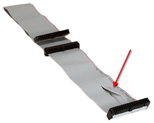
There is a twist of a few lines in this floppy cable. Why? What is the purpose of it?

totymedli
Posted 2014-12-05T19:36:05.700
Reputation: 4 004
72
7
There is a twist of a few lines in this floppy cable. Why? What is the purpose of it?
totymedli
Posted 2014-12-05T19:36:05.700
Reputation: 4 004
15
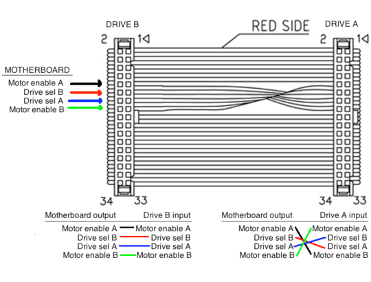
The drive before the twist will be drive B while the one on the end will be A. This way, there is no need to "configure" the drives which drive (A or B) are they going to be and what they should listen to. They can be configured identically and the twist will swap the controlling input for them.
Or quoting sawdust, from this comment:
The cable twist allows both floppy drives to be configured identically (for drive selection) when installed (for manufacturing convenience), yet operationally, can be uniquely selected as either the first drive or the second drive based on cable position.
The twisted pins are from pin 10 to pin 16.
Without the twist, we have to configure the drives and set them to be drive A for one and B for the other, because when the motherboard selects for example drive A, both drives would receive the select signal if they are both configured as a drive A. To avoid this, we should setup them by jumpers or by hard-wiring their role so there would be a drive set to be drive A that would listen to signals on the select A wire, while the other drive would be drive B that would listen to signals in select B.
This is totally doable, but we don't want to mess with the setting of the drives, just want to throw them into the PC case and plug in the cables.
Let's say both drives are hard-wired to be drive B. Now we don't have to setup them, but they both listened to the select B signal, while the motherboard would still want to send a signal to select A to select drive A. Here comes the twist! After the first drive, we twist the select cables so the drive A (that is still a hard-wired drive B) will listen to the select A controls, because we connected the select A pin to its select B pin (the only pin it listens to).
Now the drive before the twist will work as a drive B listening to select B signals, while the drive after the twist will work as drive A listening to select A signals. They're both hard-wired drive Bs that listen to their select B pin, but for one drive we connected the select A pin to its select B so the motherboard can control it through the select A bus.
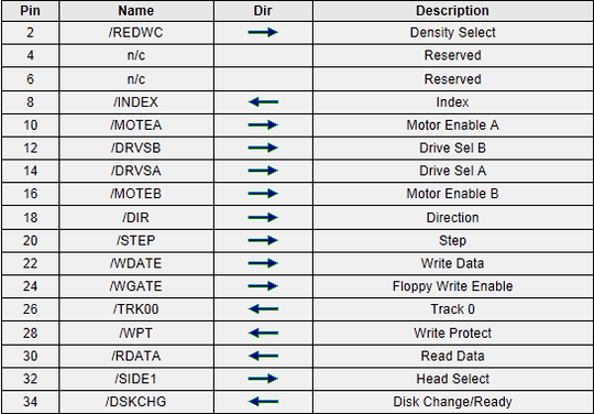
The pins are in fact "Drive Select A", "Drive Select B", "Motor Enable A", and "Motor Enable B". The twist swaps Drive Select A<->B (pins 14 and 12, respectively) and Motor Enable A<->B (pins 10 and 16, respectively). All are outputs on the floppy controller and inputs on the drives.
and here:
The rest of the pins (read and write data, stepper motor control, head select, etc.) are bussed in the normal fashion, which is why the drive select pins are so critical. A drive has to ignore all input and produce no output when it's not selected
While hard-wired drives are usually a drive B, there is the chance to be a drive A as said by Tonny here:
I once had a whole afternoon of entertainment trying to figure out why a drive which came from a working system wouldn't work in another computer... It turned out to be hardwired for A and the original computer used a normal cable, but had the signals twisted on the motherboard itself!
Also, please note what Michael Hampton wrote here:
Certain non-PC-compatible systems (like the Radio Shack Color Computer) did actually use floppies without the cable twist, but required manually setting the jumpers, and could indeed use four drives at once. While this hack allows for the end user to not have to mess with jumpers, it also restricts the system to two floppy drives.
totymedli
Posted 2014-12-05T19:36:05.700
Reputation: 4 004
2A picture is worth a thousand words! +1 – Ricardo – 2014-12-11T11:22:29.507
43
if this is a floppy cable that twist serves to select how the first (before twist) and second drive (after the twist) will be A:or B:
from http://www.pcguide.com/ref/fdd/confCable-c.html
You will also notice that there is an odd "twist" in the floppy cable, located between the two pairs of connectors intended for the floppy drives. Despite the fact that this appears to be a "hack" (well, it really is a hack), this is in fact the correct construction of a standard floppy interface cable. There are some cables that do not have the twist, and it is these that are actually non-standard! What the twist does it to change the connection of the drive on the far end of the twist so that it is different than the drive before the twist. This is done to cause the drive at the end of the cable to appear as A: to the system and the one in the middle to be as B:.

Aragorn
Posted 2014-12-05T19:36:05.700
Reputation: 1 310
2The drives themselves can have a switch or jumper that allows the drive to operate as either drive A or as drive B. Drives that can't change by switch/jumper are hard-wired for drive B. At least usually... I once had a whole afternoon of entertainment trying to figure out why a drive which came from a working system wouldn't work in another computer... It turned out to be hardwired for A and the original computer used a normal cable, but had the signals twisted on the motherboard itself! Thanks Olivetti, for wasting half a day of my life. – Tonny – 2014-12-08T15:08:08.717
32
On the PC floppy-drive cable, one of the wires is activated when a request is made to access drive A:, and another is activated when a request is made to access drive B:. Additionally, one wire is activated when the drive A: motor should turn on, while the other does likewise for drive B: (obviously when code is going to want to access drive A: it's going to turn on the motor, but having separate motor-control wires will mean that code which wants to access drive A: now but will be wanting to access drive B: again can turn on both motors). While it would have been possible to use jumpers on each drive to indicate whether it should respond to the first or second set of wires, standard practice has been to have all drives configured to respond to the drive-select and motor-start wires associated with drive B:, but then have a cable twisted between the two drive connectors so that the drive attached to the far-end connector will see the drive B: select wire when the controller is activating the drive A: wire.
While it might seem a little backward to have the drives respond to the drive B: wires in the absence of a twist, doing things that way makes it possible to use the full length of the cable when connecting a single drive A:, without requiring that the cable be twisted both before and after the middle connector.

supercat
Posted 2014-12-05T19:36:05.700
Reputation: 1 649
The cable twist allows both floppy drives to be configured identically (for drive selection) when installed (for manufacturing convenience), yet operationally, can be uniquely selected as either the first drive or the second drive based on cable position. – sawdust – 2014-12-05T21:58:41.773
@fluffy -- There are no such "Receive A, Send A" signals on the floppy interface. You're just making stuff up. – sawdust – 2014-12-05T22:01:11.327
2The pins are in fact "Drive Select A", "Drive Select B", "Motor Enable A", and "Motor Enable B". The twist swaps Drive Select A<->B (pins 14 and 12, respectively) and Motor Enable A<->B (pins 10 and 16, respectively). All are outputs on the floppy controller and inputs on the drives. – hobbs – 2014-12-06T05:07:54.413
2The rest of the pins (read and write data, stepper motor control, head select, etc.) are bussed in the normal fashion, which is why the drive select pins are so critical. A drive has to ignore all input and produce no output when it's not selected. – hobbs – 2014-12-06T05:13:01.203
@hobbs: Thanks; I'd thought two of the pins were select and the other two were unused or ground (twisting just two wires cleanly and ensuring they lie flat would be harder than twisting four) but it makes sense to allow the computer to turn on a drive's motor even when the drive isn't selected (e.g. so that operations using both drives can leave both motors on continuously). – supercat – 2014-12-06T16:09:25.363
yeah, the info was more for @fluffy than you I guess :) – hobbs – 2014-12-06T18:30:21.890
@hobbs Thanks for clearing up my misunderstanding. I should have consulted an actual pinout before I commented. :) – fluffy – 2014-12-06T22:31:41.487
@totymedli: Better? – supercat – 2014-12-08T16:11:18.507
@supercat Better, but I ended up writing a summarizing answer from all answers and comments. – totymedli – 2014-12-08T18:44:33.753
7
IBM made the kludge to allow floppy drives (in mainframes) to be changed without need for jumpers. There is also a little cut in most cables to prevent more than one drive from running at the same time - reducing the motor select signals available on the cable. The original spec IBM worked from (the drive mfg's standard) had two cables allowing 4 drives. Their cheap power supplies couldn't handle more than one drive at a time so the hack was done. The cable lunacy carried over to the PC market and became a defacto standard. Later systems could order drives in the BIOS and had no need to "sequence" floppy access. God, I feel old.

user396464
Posted 2014-12-05T19:36:05.700
Reputation: 87
I'm pretty certain that programs that did a lot of access to both floppies in near proximity could leave both drives running. I'm also unclear how a cable cut would prevent both motors from being enabled simultaneously; that would seem like either a hardware restriction on the controller card or a software restriction in the BIOS. – supercat – 2014-12-06T16:11:16.440
3Certain non-PC-compatible systems (like the Radio Shack Color Computer) did actually use floppies without the cable twist, but required manually setting the jumpers, and could indeed use four drives at once. While this hack allows for the end user to not have to mess with jumpers, it also restricts the system to two floppy drives. – Michael Hampton – 2014-12-07T18:17:08.100
9You can tell apart quite easily by looking at them... Floppy cables have a twist in them, PATA/IDE cables don't. ;) – Ƭᴇcʜιᴇ007 – 2014-12-05T20:10:22.243
Yes, after a few searches I found it out, but (until now) I never realized that this happens only at floppy cables. – totymedli – 2014-12-05T20:12:50.730
Still remember working with these. My old eMachines desktop uses SATA, but actually had PATA and floppy connectors. Managed to pull the data off a really old 2.1 GB hard drive this way (the machine was running Linux at the time). That old machine's seen quite a few upgrades, including a 400W PSU, 3.4 GHz dual-core Athlon II, and Radeon HD 7750 graphics card. – bwDraco – 2014-12-05T21:27:19.233
13"You can tell apart quite easily by looking at them... Floppy cables have a twist in them, PATA/IDE cables don't." -- The proper way to tell them apart is by the number of conductors. PATA has a 40 pin connector, while floppy has a 34 pin connector. – sawdust – 2014-12-05T21:45:05.260
floppy not exist anymore or oh sh...
– crazypotato – 2014-12-08T20:50:24.767