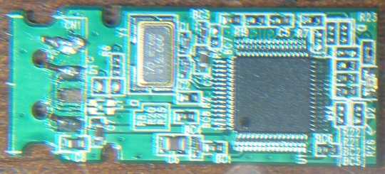
My answer assumes you soldered your wires directly to the PCB (somewhere after the plug). The hope is that if you solder wires farther back (at the ESD clamps, if they exist), then you'll have better results.
Using the plug pinout provided by Wikipedia (the 'plug' is usually on the device, and the 'receptacle' is on the board accepting your device), I would open your device and follow the connector's data pair back on the PCB.
The traces should lead to a four-pin or six-pin clamping device(s), devices usually used to prevent ESD spikes from getting onto the PCB. Chances are the PCB broke at the plug connector, which means the traces at the clamp device are still 'good'. If you can see the data pairs make a physical connection to the clamp chip(s), you should be able to solder twisted wires from it to a receptacle connection on an extender cord (receptacle <-> plug). Make sure they are twisted to mimic differential routing on your PCB.
Now, you just need power and ground connections. I suspect the ground and power pins on your broken plug are still good, so wire them directly from your broken plug to the cable.
With this complete, you've just replaced the plug. If you've soldered the connections correctly, and the traces are good (if the data pairs were broken at the plug, not the clamp), you should be able to plug your receptacle <-> plug cable into a laptop or PC to retrieve your data.
Good luck!

Is there any way you can take a zoomed in picture of the device? – xxl3ww – 2009-12-15T14:46:34.333
4"In the past I have had great success with..." Uh... how many USB flash drives have you broken in this way? Have you considered that maybe you should be gentler with these things? ;) – retracile – 2009-12-15T14:56:36.550
heh, I am an IT technician in a large school. Added a slightly blury picture. – Richard Slater – 2009-12-15T15:26:16.010