How do I attach this multi card reader to my motherboard?

2

I have an old mutli card reader taken from a Fujitsu Seimens Scaleo P.
I am trying to attach it to my Gigabyte GA-B75-D3V.

I have tried to attach this to the COM port on my motherboard - it doesn't fit in the front USB sockets or regular USB sockets.

The connector on the reader is shaped like this:

.::::.

Here's an image of it:

enter image description here

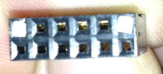
Four pins on top row and two closed "pin holes" and 6 on the bottom row.

Does anybody know how to connect this up?

Do I need some sort of converter?

edit: I have added another image of the connector from the site showing the four wires going in. A red arrow illustrates whith socket with a white peg has a little arrow on it. Hope this clarifies things a bit.

http://imgur.com/aPHKm

enter image description here

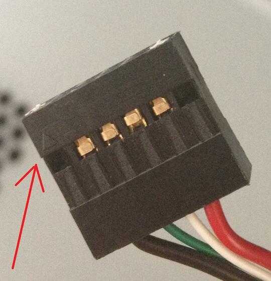
The row of six holes can be disregarded.

If needed I have additional images and a few images of the f_usb sockets on my motherboard, that I can upload on request.

jaget

Posted 2012-08-06T13:16:16.440

Reputation: 153

You would need to figure out, wether it is USB + power or whatsoever. Maybe the connector is custom, so you would need to attach it using a different connector. In the end it could be easier and cheaper to buy a new one. – None – 2012-08-06T13:29:54.037

I've added an image to clarify (poor quality image but should be clear enough) – jaget – 2012-08-06T14:21:17.093

Which holes have wires? Which hole is "Pin 1" (often marked by an arrow on the plastic)? – Ƭᴇcʜιᴇ007 – 2012-08-06T18:34:15.217

The middle four on the bottom row in the picture. I'll find out more when I get home. – jaget – 2012-08-08T14:32:36.520

Answers

3

I dont want to say this, but that looks like a USB hub connector. It is a place on your motherboard that you connect extra USB hubs. Looks like: Image Try connecting your card reader to the USB hub port on your motherboard. Keep in mind this is NOT the USB port on your case, it is a connector on the motherboard for adding additional USB hubs.

Wolfizen

Posted 2012-08-06T13:16:16.440

Reputation: 1 122

would I need to remove the white pegs that block of the far left and far right connectors on the top row? – jaget – 2012-08-06T16:14:12.520

I have had a closer look it has four wires which are red white greed and black. – jaget – 2012-08-06T18:07:30.040

Yes. Remove the white pegs – Wolfizen – 2012-08-06T18:59:04.680

So what type of connector is this if it only has four wires in ten holes (6 of which being empty) – jaget – 2012-08-07T00:42:10.463

I honestly don't know. I was just guessing the port. – Wolfizen – 2012-08-07T04:01:59.610

2

The motherboard internal USB connector (which can be used for a USB hub, but I think that's actually much less common than use for internal card readers, connecting front panel ports on the case, etc.) usually is 2 rows of 5 pins, with one corner pin missing, which is 2 four-pin USB root ports. The extra column is used to help with orientation.

Your cable looks compatible with this, without removing the white fillers, although I would compare the pinout to the manual for the motherboard, to make sure the orientation is correct. Your card reader only needs one of the two ports on the connector, hence the second row is left unconnected in the cable.

Be careful because there's also a 2x5 connector for front panel audio on most motherboards. You can tell them apart either by reading the silkscreened labels, or because the audio port has one of the center pins missing instead of a corner.

Ben Voigt

Posted 2012-08-06T13:16:16.440

Reputation: 6 052

0

Late answer, but maybe helps somewhat. This is a special dual channel USB connector which supports USB smart card readers. It has a special pinout.

You can find some old Fusitsu Siemens MoBo with this pinout. Check e.g. the manual of D1931: http://uk.ts.fujitsu.com/rl/servicesupport/techsupport/Boards/Motherboards/Fujitsu/D1931/A26361-D1931-Z120-UK.pdf (page 16.)

szmt

Posted 2012-08-06T13:16:16.440

Reputation: 1