Soldering a SATA-Data cable to a HDD

18

3

I tried to clean my computer and accidentally ripped of the SATA cable from the HDD which resulted in a broken SATA data port because the "L" on the HDD broke off and was stuck in the cable. I wanted to replace my HDD anyway since it is very old and I have backups but a very few new things (like some unused web designs or some documentations) are not saved yet and I'd like to try to save them. (But its not suuuuuper important.) I'm aware of the fact that this HDD will not be good for actual use anymore, so after saving the files it will get replaced immediately.

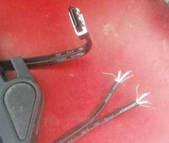
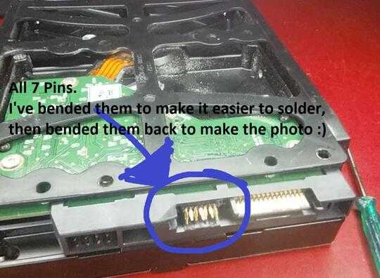
On the HDD are (luckily) all 7 pins looking out (no pins have broken off) and I casually tried to solder it, as I solder everything quite sucessfully when some of my parts get broken, but I noticed that the cable has 8 instead of 7 pins...

Here some pictures:

(8 Pins ???) This is the cable with both sides (1 side stripped off to solder it)

cable with both sides

(7 Pins) This is the HDD with the broken SATA data connector

HDD with the broken SATA data connector

I googled and I find that the SATA Data cable indeed needs only 7 pins, so now I'm wondering how I can find out which one I have to solder and which one has to stay unsoldered. Are the pins on the cable even in the right order? (For example: the rightmost pin from the cable goes to the rightmost pin of the HDD SATA data connection)
Milos

Posted 2017-05-08T00:42:31.880

Reputation: 181

60Stop bending them! (You have used up 2 of about 6 bendings available.) – AndreKR – 2017-05-08T03:53:44.773

1You might be better of getting a new PCB from eBay. It has to be the same make, model and revision. – Daniel B – 2017-05-08T08:00:56.777

35You have not bended them, you have bent them :) – Hanky Panky – 2017-05-08T08:43:05.783

2Thanks @HankyPanky, you seem like someone who shares very useful tips to this Community :) – Milos – 2017-05-08T08:44:51.737

@Daniel B make this an answer, since it is a very viable solution to the problem. – rackandboneman – 2017-05-08T09:04:37.530

Look at Journeyman's answer for the SATA pinout... The cable you have is composed by two "emi"-cables. One has the A+/A- couple and two grounds, the other has the B+/B- couple and two grounds. Usually the two innermost grounds are tied together, so no wires are left unconnected. You can just try, but I think that your pins will break easily.. Better solder on the pads on the PCB – frarugi87 – 2017-05-08T10:36:32.027

I'd pull the drive from what looks like a cradle in your photo and try to solder to the PCB contacts behind the smashed connector. – John U – 2017-05-08T12:58:35.253

5Just toss the disk in the trash. You've got backups, right? Oh... – Roger Lipscombe – 2017-05-08T14:31:42.573

When this happened to me last year, I was still able to hard slide the pins into the SATA cable. I then strategically just super glued and hot glued the cable. It worked well enough that I was able to clone the drive to another. Could still possibly go that route. – TyCobb – 2017-05-08T20:30:22.390

I think you will have the best luck taking the whole interface assembly from a donor drive and unsoldering them both from their PCBs, then resoldering the complete one to the PCB you want to repair. With a solder wick you should be able to do it and maintain the intregrity of the connectors. – PhasedOut – 2017-05-08T22:12:19.200

Answers

29

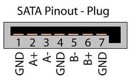
Actually, there's only 4 pins that matter

image of pinout of sata plug

You have 4 wires for signal, 2 per 'channel' and 3 grounds (which should be tied together anyway). The 4 bare wires on the outside of each pair/channel are ground, and any three should work.

You absolutely do not want to do this without a multimeter.

That said, I strongly recommend plugging one end into a switched off PC or drive and checking continuity between all 4 ground wires (on the outside) and checking each pin and its corresponding wire to ensure you know which wire is which. If you don't have a multimeter, you ought to get one and learn the basics of using it - continuity testing is about the simplest function in one.

I'm also not sure if trace lengths matter here, and that may be an issue. Not sure how to deal with that considering everything I've seen in the question though

Journeyman Geek

Posted 2017-05-08T00:42:31.880

Reputation: 119 122

16

Actually the GNDs can be important at high frequencies: https://electronics.stackexchange.com/questions/180811/why-do-cables-have-multiple-grounds

– PlasmaHH – 2017-05-08T08:46:11.513

@PlasmaHH Some protocols will slow down if a low-quality cable is causing problems. I don't know if that is the case with SATA. If so, it may be sufficient to clone the hard drive. – user253751 – 2017-05-08T11:20:14.720

19@user20574: The slowest SATA frequency is 1.5GHz where you already get transmission line effects, so leaving GND unconnected without a dire need is not going to end well. Especially when you talk about data recovery, you want the data without errors, and error correction on SATA is not stellar. – PlasmaHH – 2017-05-08T11:32:53.467

9I actually did it once, using GND too but only one of the pins to avoid ground loops... And I'd recommend to use an external usb-to-sata converter instead of plugging the frankencable to an actual motherboard. – Alex Mazzariol – 2017-05-08T12:28:31.530

2@AlexMazzariol "but only one of the pins to avoid ground loops" - this makes no electrical sense whatsoever for a SATA cable. PlasmaHH knows what he's talking about - you were just lucky. – brhans – 2017-05-08T22:04:37.323

@brhans: I'm no electrical engineer, but why would that make no sense? The 3 pins are connected together on the controller board and on the motherboard I was using, so there was no need to connect the 3 of them to the shield of the shielded cable I was using (it was NOT a sata cable, more on this in my answer). I could probably totally avoid to connect the GND line from the signals connector altogether, since that was connected to the power GND line too and it came from the very same motherboard. – Alex Mazzariol – 2017-05-09T18:04:49.367

"switched off pc" = hard shutoff switch on the PSU or unplug it. Motherboards are powered to a certain extent when "off" – Yorik – 2017-05-09T19:18:30.287

only 5v standby. And I wouldn't feel comfortable telling people to tell people to short random data cables in a plugged in PC. Abundance of caution and all that. – Journeyman Geek – 2017-05-09T23:50:41.423

The fourth ground is probably for any metal housing bits of the plug. -- Might be best off just soldering a fresh connector on to the drive. https://www.digikey.com/products/en/connectors-interconnects/pluggable-connectors/443?k=SATA&pkeyword=&FV=ffe001bb&mnonly=0&newproducts=0&ColumnSort=0&page=1&quantity=0&ptm=0&fid=0&pageSize=25

– BrainSlugs83 – 2017-05-09T23:52:03.477

24

Don't try to strip and solder a SATA cable. It's unlikely to work; the wires have some really touchy electrical properties.

Instead, flatten the contacts back out, get a fresh SATA cable and carefully line the bare copper contacts from the hard drive up with the contacts in the cable. If you apply pressure in the right way, you should be able to establish a connection long enough to recover your data.

duskwuff -inactive-

Posted 2017-05-08T00:42:31.880

Reputation: 3 824

6"the wires have some really touchy electrical properties." - Could you please explain this further? Because I already stripped them and soldered it but the HDD doesnt seem to get recognised by my system even tho I triple checked every connection and re-soldered it. Im not an electrical engineer (but I have all the equipment) but I cant see what the problem should be when wiring them with normal wires? Thanks a lot :) – Milos – 2017-05-08T08:18:38.187

6@Milos its things inherent to all high-speed data buses, but I think one of the major things here will be that special measures are taken to ensure all data lines are of exact equal length, just cutting, stripping and soldering the cables individually will almost definitely have violated this and made the connection unlikely to work. – Trotski94 – 2017-05-08T08:55:27.727

3@JamesTrotter: With SATA 3.2 we talk about ~2cm wavelengths so anything up to 2mm mismatch can work and anything with .5mm is basically guaranteed to work. Multiply those numbers by 10 for SATA 1. The most likely reason this won't work is that at the point where things are soldered you have a gross impedance mismatch. SATA Plugs are actually manufactures to stay within the specified impedance. – PlasmaHH – 2017-05-08T11:45:16.370

3I can endorse this recommendation. I was able to recover from a similar mishap with an SSD this way a few years ago by carefully reinserting the cable with the broken stub of the device connector back into place and securing it with tape. – Dan is Fiddling by Firelight – 2017-05-08T13:53:35.063

1This is a great answer. As @PlasmaHH mentions, SATA 1 would probably be (slightly) more tolerant to impedance mismatches, so it might be worth investigating if there is a way to select that in your BIOS, or if you have an older SATA expansion card that only does 1.5 Gbit/s. – pipe – 2017-05-09T15:34:44.550

SATA1 to USB adapter might also work. – BrainSlugs83 – 2017-05-09T23:55:50.163

15

Instead of trying to fix it, you could also try and get a new PCB for the disk. They are very easy to swap. You can look on eBay for replacements, for example drives with mechanical failure.

However, for best results, the PCB needs to come from an equal device:

  • Same make
  • Same model
  • Same hardware revision

Most of the drive’s firmware is actually stored on the disk, so the firmware version isn’t that important.

/edit: However, it appears there is some unique calibration data that is required for most modern hard drives to function properly. It is unique to each unit. There are PCB replacement services that offer to transfer the data for you.

Daniel B

Posted 2017-05-08T00:42:31.880

Reputation: 40 502

9For many hard drives, this absolutely won't work because the calibration table is stored on the PCB. – David Schwartz – 2017-05-08T17:02:14.723

@DavidSchwartz Thanks for the warning! Could you help me verifying if it is possible to replace the PCB on my HDD? The PCB Board I would need is 2060-771824-008 for the HDD WD10EZRX from Western Digital (http://www.hddzone.com/wd-2060771824008-pcb-p-477.html) Thanks in advance :)

– Milos – 2017-05-09T08:32:33.607

2@DavidSchwartz PCB replacing is a common last-effort data recovery technique for drives that don't spin anymore (before sending it off to a real recovery company with clean rooms, etc...). I usually tried to match everything on the PCB's, even down to the year the drives were made or even closer if possible. Firmware versions matter, along with everything else. I've done this a handful of times, and sometimes it works sometimes it doesn't. – SnakeDoc – 2017-05-09T18:25:05.780

9

Exact length of all conductors is not as important with serial-lane buses like SATA or PCI-E, compared to eg parallel SCSI. But keeping both wires of each differential pair same length, not separating the wires from each other and associated shields more than necessary for more length than necessary is essential. https://sata-io.org/system/files/member-downloads/SATA-6gbs-equipment-design-and-development-finisar.pdf suggests specs like 4.5GHz(!!!), 50-100ps risetime(!!) on a sata cable. Whether the actual base frequency of the signal is 4.5Ghz is near irrelevant - if the modulation scheme needs bandwidth to that degree, it needs it. The wavelength of a 4.5GHz signal on a common cable will be 4 to 5 centimeters.

A common rule of thumb in working with AC signals is that a wire longer than 1/10th of the wavelength (this would be 4mm here) can no longer be treated as "just a wire", since the same effects that will make "just a wire" suddenly act as a coil, antenna, or capacitor plate (none of which you have any good use for here) will start to predominate over "just a wire" behaviour.

For example, a an extra quarter-wavelength (about half an inch at 4.5Ghz) piece of cable with nothing connected to the other end, soldered in parallel to the signal wires, would be expected to be just an open circuit. Far from it. This will behave as a dead short if nothing is connected to it, and behave as an open circuit if the end is shorted.

These effects are irrelevant for 60Hz AC wiring in your household since the scale is different - they will become relevant when building 60Hz lines spanning hundreds to thousands of miles, and professionals designing such systems are aware of them.

RF (you are dealing with RF here. The "coaxial cables and brass piping" kind of RF.) engineers think in pairs of wires (so called transmission lines), and the geometry and material setup of these pairs (separation distance, twisting together, insulation materials nearby even if they are perfect insulators at DC) really matter. Only if such a pair is correctly set up and KEPT at that for its whole length, OR made up out of sections that, while different in build, have the same properties (the cable vs the plug and socket - geometries and materials aren't random here!), will it behave as a cable and not as an antenna, coil, capacitor...

A solder splice disturbing the geometry for one or two centimeters is way out of (transmission) line - if this can be done at all, only removing the insulation from the cable for a few mm and soldering them on truly as short as possible stands a chance of working - in the worst case, the missing plastic material from the plug is going to sabotage your effort (this is not about insulation, but so called dielectric properties, which are way different for air vs plastic molding).

rackandboneman

Posted 2017-05-08T00:42:31.880

Reputation: 670

3I would say that the length matching is doable rather easy, the impedance mismatch at the solder point when soldering bare wires to the broken connector is what will destroy the signal. Removing that broken connector and soldering the wires directly onto the pcb has the highest chances of success, I would expect the link training to compensate for the rest. – PlasmaHH – 2017-05-08T11:50:04.887

Absolutely. Or getting a shape compatible connector from another scrap harddrive and soldering it in. – rackandboneman – 2017-05-08T11:54:10.110

You can just buy the connectors. -- They're cheap. – BrainSlugs83 – 2017-05-10T00:00:37.207

6

I did it once, on a homebrew hack-it-all frenzy on an old (~2010 maybe?) toshiba laptop motherboard towards the original SATA disk.

And it worked, and surprisingly well too. I made sure I soldered only ONE ground pin, because I was using an USB2 shielded cable and wanted to avoid ground loops (I would have had to join the 3 grounds on the same shield, and that would create 3 mini loops).

Other than that, even if it works, use an external USB-to-SATA converter to avoid frying your motherboard and, after you recovered any precious data on the HDD, throw it away (or replace its controller board like others said).

Expanding on the answers, to integrate comments to other answers from other people: GND may not be required, because the signals are balanced, but I'd strongly recommend connecting it. Using an external USB-to-SATA converter may help you forcing a SATA 1 connection, which has larger tolerances towards relative cable lengths, other than preventing harm to the controller of the motherboard in case of misconnections / short circuits.

Alex Mazzariol

Posted 2017-05-08T00:42:31.880

Reputation: 267

I have also done this successfully. I used a lot of hot glue to provide strain relief for the connector, which came in handy years later when I tried to "unplug" the soldered connection when removing the drive (having long forgotten the soldering). – Ben Jackson – 2017-05-10T08:07:53.520

I wouldn't really recommend to use such a setup for long usage... But it may reaaaaally help if you happen to not have a recent backup. – Alex Mazzariol – 2017-05-10T08:30:30.607