We are working on the same issue here with what looks like an 8100 Elite with a PS-4321-9HA and seeing if we can't get it hooked up to an ATX PSU.
From the silkscreen on the PCB of the PSU (4321-9HA):
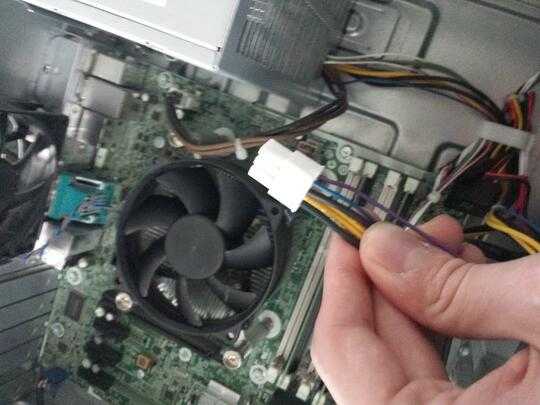
Yellow is Mainboard 12V
Brown is CPU 12V
Blue is -12V
Purple is +12V Standby
Black is GND
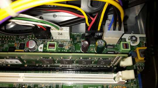
Now that little white header there that is called "P2":
Black = GND
Green = PowerON (ATX standard color - when did we start doing that?)
Grey = PowerGood (again, standard color)
White = something labeled TAC - which I assume is tachometer and goes straight into the fan.
White&Red = FANCMD - yip yip yip.
Now PowerON handling, as mentioned above - could be different.
The chip is a Silicon touch PS25A - datasheet
Now how is that different and how do we spoof a standard ATX power supply into thinking that it's connected to a standard motherboard and the other way round?
-------> working on it
stuff to do:
Make step-up converter from +5VSTBY to +12VSTBY
Make PCB with ATX 24 pin header that goes into
motherboard and translates powerON and powerGood back and forth between the devices. ->EDIT: Just bought an ATX extension cable and soldered and shrinkhosed them together.
Meanwhile, on the PSU board, other chips used are: CM6802AHG, TL5940N, TNY279PN - I thought TNY might be an ATTiny or something like that but whew no microcontroller. We are in analogland all the way.
So far, good news. Reading up on this controller chip here - PS25A - looks like it's just the standard +5V and 0V with a 1.5V threshhold for high and low and all that might be an issue is current sinking, I saw the standard ATX PSU deliver more current through Power_On than this one here. Perhaps that is where the difference is.
***Got it working :) Took it to Conrad and showed it to Ronald and ...
Nothing special. Datasheet shows basic PSU design, the chip is a very classic circuit. Apart from fan control and stuff (can be omitted) there is nothing different re standard ATX which means I got myself an ATX header cable and soldered this to that and that to that and Bob's your uncle. More elaborate stuff later but for the moment, that's a wrap.
If you do this yourself - cut the original HP plug off the original PSU so that your colors are on the right pins and then from the ATX PSU get an ATX header and wire grey to grey, black to black, blue to blue, green to green, just fine, but USE THE HP little plug you cut off the original HP PSU because indeed the pins are different from anything standard ATX. Colors are identical except for
Purple
which is 12VSTBY. If you don't have 12VStby use a DC DC stepup converter or a wall wart PSU to get you started, wire + to purple, -/GND to black/PSU Ground and in you go. Plug it in, small green LED on motherboard should light, then you can turn on the main switch and board should fire up and give you a
515 fan not detected.
Apart from that, looking good here.
Gonna install chipset drivers next but that's not my job anymore. :)
Have fun, Lukas out.


From a quick google search the PSU dosen't look standard - I found a service manual online http://www.manualslib.com/manual/550218/Hp-Prodesk-600.html, and that confirms it uses an oddball 6 pin power connector. I would not plug in a pci-e 6 pin connector without checking first
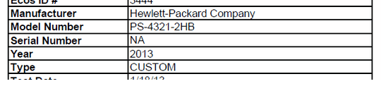
– Journeyman Geek – 2015-01-26T12:54:33.800Forgot to add, I have the tower version of that PC, however, the PSU probably is the same, model number is PS-4321-2HB. And that's why I'm checking here, if maybe someone knows... – Squeazer – 2015-01-26T12:58:07.067
1Could you add an image of the connectors? I'm hoping the colours are standard – Journeyman Geek – 2015-01-26T12:59:28.977
1I see black and yellow, which are standard, and blue and purple which arn't. – Journeyman Geek – 2015-01-26T13:19:49.170
Purple is +5VSB (standby power), while blue is -12V. The -12V rail, in particular, is not all that often used in modern hardware and many boards don't use -12V at all. Obviously, HP is doing something nonstandard here. – bwDraco – 2015-01-27T18:16:56.967