4
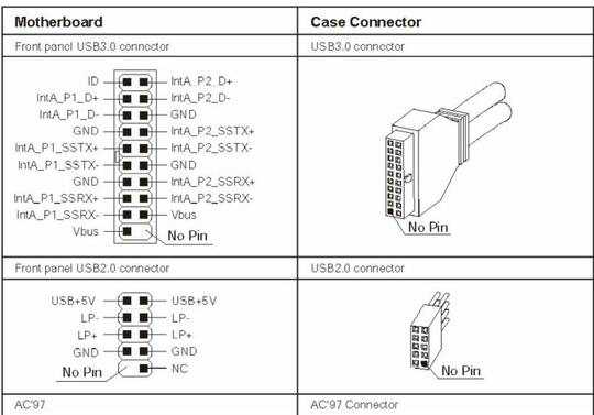
While researching how to use my new motherboard with a 20pin USB3 header with my USB2 cables (so i wouldn't have to wait for yet another delivery), the farther i could go was this image

if i understand this correctly, the 20pin header has for each USB3 port:
- TX (D+ in pic)
- RX (D- in pic)
- GND x2
- extra_TX+
- extra_TX-
- extra_RX+
- extra_RX-
- +5V
plus a shared ID pin.
the older USB2 header, had for each port:
- +5V+
- TX
- RX
- GND
the USB2 maps 1:1 to the final usb port... but the USB3 for me is just crazy! and I really doubt if I crack open a chinese USB3 20pin cable i will find much more than just a wire going from a few select 4 pins...
The question is: Why does it have all those pins if the ultimate connector only have 4 pins anyway?
Edit:
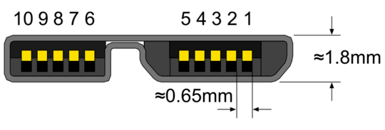
ok, apparently i missed a pic on wikipedia that cames with no explanation besides the pinout, that hints we will have a (as far as i can tell from the pic, idiotic) 10pin wide full-USB3 connector at some point...
http://en.wikipedia.org/wiki/Universal_Serial_Bus#Physical_appearance

So, new question, is it safe to just use the 4 pins that the current usb ports use from the 20pin header? as the original question stands: the ultimate connector going out of the case only has 4 pins... why do i need to connect more on the internal plug if they are just going to be forever unused?


Huh? USB 3.0 has 4 extra data lines. – Breakthrough – 2012-12-18T00:21:51.333
Using only 4 pins will limit it to USB 2.0. That is why USB 3.0 is backwards compatible. – Fiasco Labs – 2012-12-18T00:52:39.413
You shouldn't edit your question to ask another question. If you've found the answer, then answer it your self. If you have another question then ask it, instead of editing your question as a new one. – James Mertz – 2012-12-18T01:52:01.280
The 20 pin header is for two USB3 ports. One port down the left side and the other down the right side. – Brian – 2013-01-02T04:10:18.957