Introduction
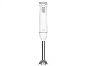
I'm Yuhan, and this guide was created to complete the teardown assignment for Assignment 2 of UNSW's Industrial Design - IDES 2323 course. Here, I will describe the process of tearing down a stick blender.
-
-
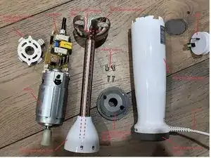
Blades:Stainless Steel (SS304)
-
Power:600W
-
Turbo Function:Yes
-
Power Supply:220-240V ~ 50-60Hz
-
Unit Dimensions:62 (w) x 62 (d) x 395 (h) mm
-
Weights:Net: 0.7 kg / Gross: 0.84 kg
-
-
-
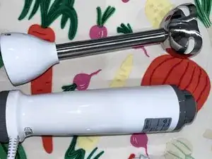
Turn the handle section face up.
-
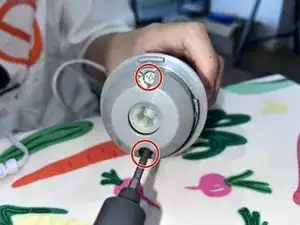
Locate the two retaining screws at the top (as marked by red circles in the picture).
-
Use a screwdriver with a Phillips head (as marked by yellow circles in the picture) to unscrew the two screws.
-
-
-
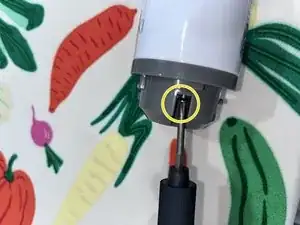
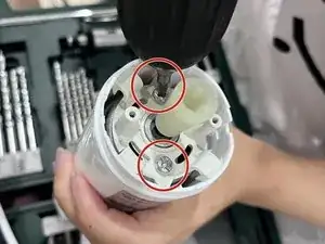
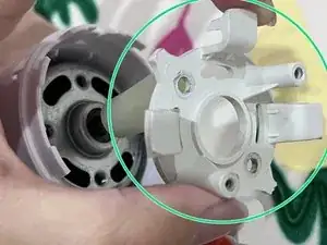
Locate the two fixing screws for the internal white fixing parts and unscrew them with a Phillips head screwdriver (as marked by the red circle in the picture).
-
-
-
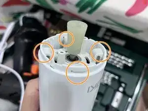
This white internal fixing part is held to the housing by four snap fastening devices as shown by the orange circle in the figure.
-
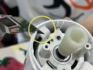
Use a knife to completely cut off a portion of the plastic housing above the snap (marked by the yellow circle in the picture).
-
Remove the white internal fixing parts after successfully disengaging the clips from the housing.
-
-
-
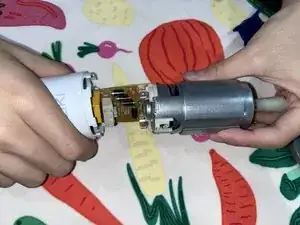
Pull out the internal motor and connected circuit boards by hand directly from the shell.
-
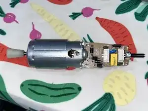
Remove the complete motor and circuit board.
-
-
-
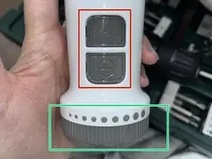
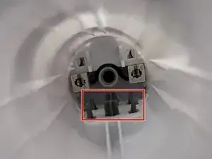
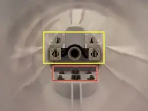
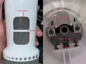
The switch button and Turbo button are labelled in the red box in the picture, and are captured in the housing from the inside by the inverted triangular end of the structure shown in the picture.
-
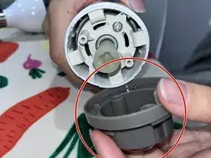
The green box in the picture shows the bottom plastic knob, and the Shell is held together from the inside and can be rotated.
-
The yellow box in the picture shows the resolver, which is fixed to the Shell with the bottom knob from the inside, while it can work by connecting the circuit board and the motor from the circular structure in the middle.
-
-
-
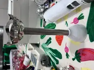
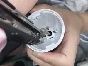
Turn the Blender section upside down so that the bottom is facing up.
-
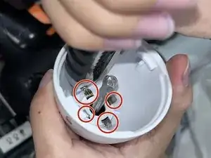
Find to four sections that have been pressed down to hold the white plastic shell in place (as marked by the red circle in the figure).
-
Use a tool to pry them both into a vertical position.
-
-
-
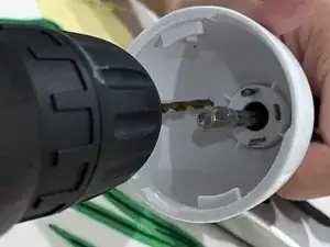
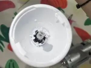
Use an electric drill to drill through the part of the plastic shell that connects to the internal blade.
-
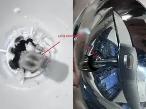
Seen inside by the opening is a blade with a long handle that is separate from the outer metal protective case.
-
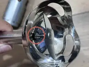
The metal blade passes from the bottom of the blender section to the top and is secured inside the protective metal casing by the clasp marked by the red circle.
-