Introduction
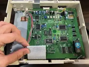
A 32-bit home video game console developed by NEC and Hudson Soft. It was released in 1994 and discontinued in February 1998. It was intended as the successor to the TurboGrafx-16. Unlike its predecessor, the PC-FX was only released in Japan. (Source: Wikipedia)
-
-
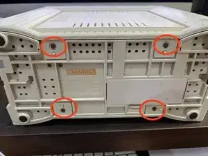
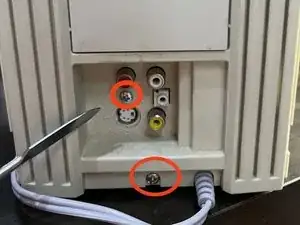
Remove the four T10 screws located underneath the console. These hold the left and right side panels in place.
-
-
-
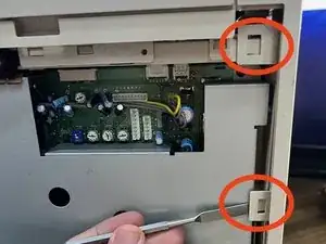
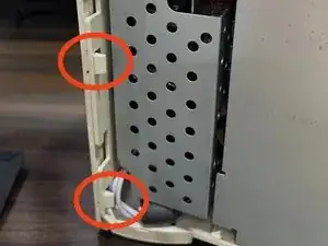
Remove the front panel attached by three clips on each side. The top two clips on the left are encircled in the picture.
-
-
-
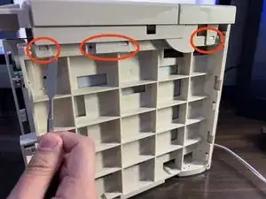
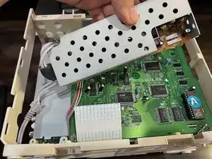
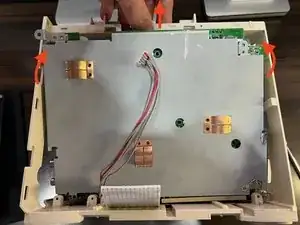
With the front panel out, lift the top panel that is attached by three clips on each side. Be aware that the top panel is attached to the daughterboard via the lid sensor connector (second picture), so do not pull it away immediately.
-
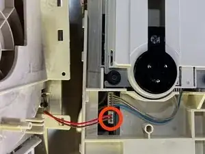
Remove the lid sensor connector in order to fully free up the top panel.
-
-
-
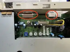
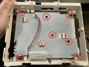
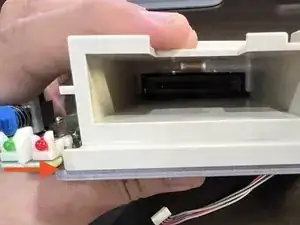
Now turn your attention to the CD drive. Lift up the tabs holding the drive ribbon connector at the left and the power connector at the right (if you haven't already).
-
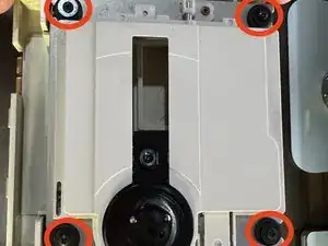
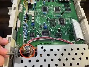
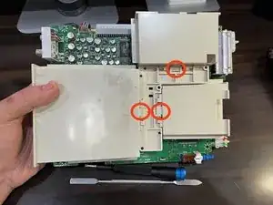
Unscrew the four small Philips screws on each post holding up the drive (encircled in the second pictur). You may now lift up the drive and remove the springs on each post underneath.
-
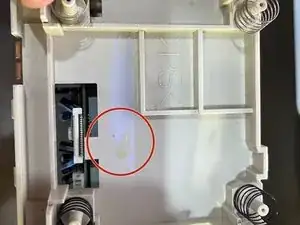
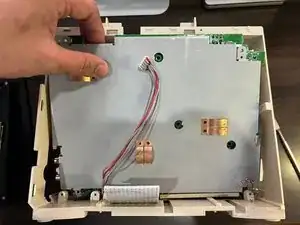
There will be a transparent plastic sheet holding the ribbon connector in place. I strongly suggest totally removing this, as this will make plugging back the drive much easier.
-
The third picture shows the remaining adhesive after from removing the clear plastic sheet.
-
-
-
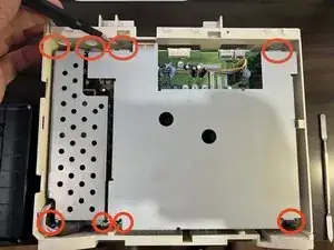
Remove the 8 philip screws encircled. For the lower leftmost screw, you will need to move the power cable out of the way. The lower rightmost screw will also be holding in a ground cable.
-
Remove the daughterboard shielding (the big one on the right of the Power Board) after.
-
-
-
Unplug the 4-pin power connector from the daughterboard to the powerboard (with yellow wire). Do the same with the 5-pin power connector from the motherboard (with red wire).
-
After this you may remove the power board. You will have to pull the whole power cable from the inside as shown in the second picture.
-
-
-
Remove the main ribbon cable from the daughterboard.
-
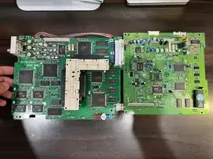
The daughterboard may then be removed since nothing else will be affixing it to the unit.
-
-
-
The trickiest part - remove the main motherboard. To do this, you will have to flex the top part of the plastic frame up while lifting the upper part of the motherboard towards you.
-
This may require some fiddling, so check from time to time if there is no frame plastic blocking the top part of the motherboard when you lift it up. If you have trouble, you almost certainly just need to flex up the top area of the plastic frame a bit more.
-
-
-
With the motherboard liberated, simple unsnap the three encircled clips of the expansion port bays. You are now done with the teardown at this point.
-
-
-
When reassembling any of the three expansion port bays, make sure that the lower "lip" fits BETWEEN the PCB and shielding underneath. Failure to do so may not allow the Rear, Top and Front outer panels to close properly.
-
When putting in the motherboard back, insert it the opposite way you took it out. Slide in the PCB bottom side first, then flex up the top frame area while pushing down the topside of the PCB.
-
After reinserting the motherboard, check to make sure that all three three expansion port pieces are snapped correctly into place within the bare PC-FX plastic frame.
-
Again, remember that when reassembling the unit, you will need to affix the panels in the exact reverse order you removed them in this guide. (Rear, Top, then Front). This is because they are interlocking.
-
Todo: Will add better pictures showing both sides of the front panel.
Paul Prantilla -