Introduction
Tools
-
-
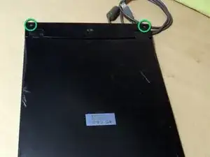
Use a screw driver to remove two screws near the cover hinge.
-
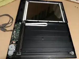
Lift the cover where the screw sat and shift it downwards gently (regarding to the image orientation).
-
-
-
The cover part holds the glass plate which also serves as guide for the sensor bar and keeps it in place.
-
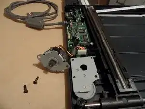
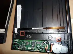
Most of the relevant electronics and mechanics is located at the left side of the lower body in this picture.
-
-
-
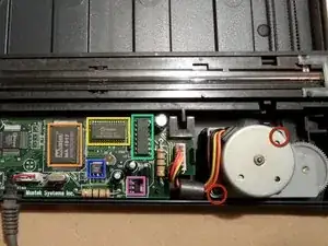
Remove two screws highlighted in red to free the motor.
-
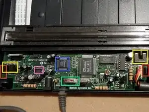
Integrated circuits in this picture:
-
Mustek MA1017
-
Winbond W24257AS-35
-
ULN2003A (Darlington Transistor Array for Motor power supply)
-
7805 voltage regulator
-
SC1202 voltage regulator
-
-
-
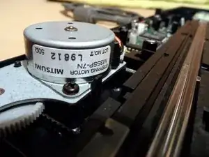
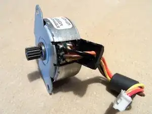
It's a Mitsumi M35SP-7N stepper motor. Probably unipolar as this model uses 5 wires.
-
As can be seen in the last image, it features 6 contacts originally and could be rewired. Thus, it also can be controlled like a bipolar stepper by ignoring the middle contacts.
-
-
-
Remove the USB cord.
-
The electronics board is hold in place by two plastic brackets. Bend them back to remove the board.
-
Integrated circuits in this picture:
-
LM324M Quad Operational Amplifier
-
Winbond W6662CF
-
2 fork light sensors, labeled H806-04
-
-
-
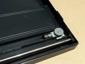
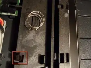
The sensor bar sits on two springs which press it against the glass plate of the cover. Without the cover it is hold down by two plastic brackets. Bend them back gently to remove the sensor bar.
-
Apparently the sensor bar is made by Canon and labeled: 0C0009913AYGG, CVA-60216K-002
-
