Introduction
This is a teardown of Logitech's wireless charging pad for their wireless mice (LIGHTSPEED ones only). Its official name is Logitech POWERPLAY.
This is a teardown I did while working on a project, so I only took it apart as far as I needed. You can see a little more (although little far away images) at FCC's database. They also tear down the pad itself to show its internals.
This teardown will briefly explain how it can be done, but mostly intended to show what parts are inside the device for reference if doing self repairs or projects like I am.
Please make a comment on the teardown if there is some information you miss, or if I made an error.
-
-
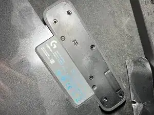
The picture shows the sticker and screws removed.
-
Option 1: You can choose to cut out holes in the sticker where the screws are if you want.
-
Option 2: You can choose to rip the sticker off carefully if you want to put it back on again, if that's what you prefer
-
Now be careful when you open it, there is a ribbon cable connecting the charging pad to the housing PCBs. See next step for reference.
-
-
-
So as mentioned in the previous step, there is a connector for a ribbon/flex cable on the charging board.
-
You need to take out the 3 screws from the PCBs then carefully take them out and disconnect the cable
-
Now you're left with two connected modules. There is a 4 pin connector that you can just disconnect.
-
That should pretty much be it for the teardown. Look at the next steps to get a closer and more detailed look at the internals.
-
-
-
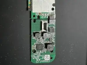
This is the main module that handles the USB-connection for the data connectivity for the wireless receivers as well as power for both the receivers and the charging module (see next step).
-
This module alone can act as a receiver for your Logitech LIGHTSPEED devices. Though I'm unsure how many devices it can connect simultaneously.
-
-
-
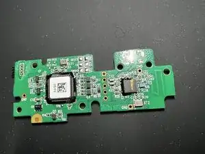
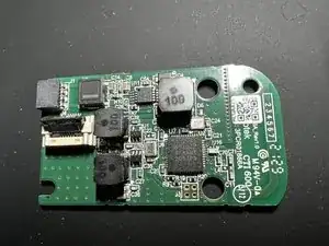
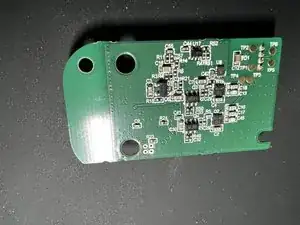
This is the charging module that connects to the wireless charging transmitter coil.
-
In the first picture you can see the connector on the left side of the board (white with slightly open lock).
-
Although I haven't tested, it should work just fine for charging if you can supply power to the 4 pin connector on the board.
-
Without being an expert on the topic, I'm assuming that the 4 pin connector is just a USB 2.0 spec connector to communicate some information from the charging module to the main module. (so 2 pins for power and 2 for data)
-
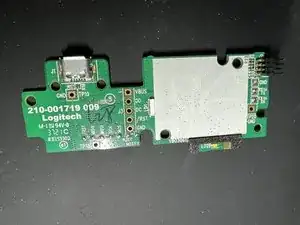
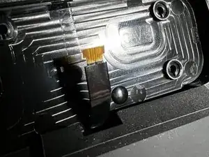
Last picture is of the ribbon cable that connects to the power output port on the charging module.
-