Introduction
The SL lineup of Lenovo ThinkPad laptops was launched in 2008 as a low-end laptop geared toward small businesses. Its launching price was around 500 Euros, or about 555 USD.
This particular laptop, the SL410 is the 14” version.
Tools
-
-
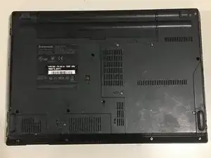
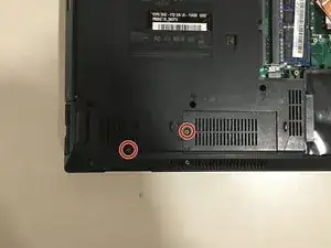
First, flip the laptop upside down. Underneath, you will see a few compartments that can be unscrewed.
-
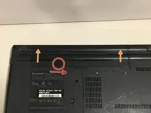
Before doing any unscrewing, though, you'll want to remove the battery (just in case)
-
First, push the battery lock to the right
-
As the battery lock is as far to the right as it can go, pull the battery out, in the direction of the two arrows
-
-
-
Now that the battery is out, we can start the rest of the teardown.
-
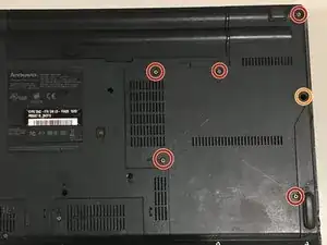
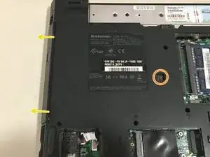
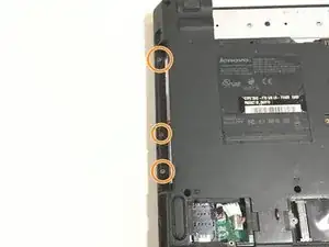
First, unscrew the six screws circled. The one circled in orange is just a little lower and harder to see
-
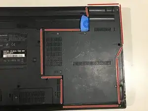
Next, take a tool like the Opening Pick and slide it in, then move it around the highlighted area to pop the panel off
-
-
-
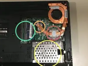
Removing this panel gives us access to the processor, graphics, RAM, HDD, and fan/heatsink
-
Processor: Intel Core 2 Duo T6570
-
-
Graphics: Intel 82GM45 Graphics and Memory Controller Hub
-
-
HDD (Hard Drive): *This model can vary, depending on if this part was replaced or not
-
The hard drive in my model has a Seagate Momentus 250GB 5400RPM drive
-
RAM: *This model can vary, depending on if this part was replaced or not
-
-
-
First, grab the small black pull tab
-
Pull the tab away from the SATA port (to the right)
-
Find the corner of the hard drive and lift up
-
-
-
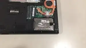
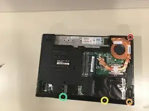
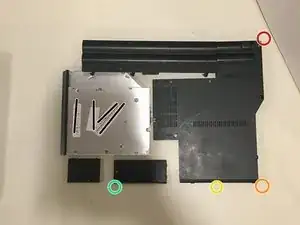
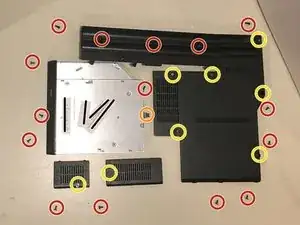
So, if these circles represented screws (image 1), the second image would depict where they would rest on the table.
-
-
-
These steps are optional too, but I will remove these parts solely because this is a complete teardown.
-
The remaining two panels both have one screw that needs to be unscrewed before the panels can be lifted up. (These screws also stick in the panel, so no need to worry about them falling out!)
-
Unscrew this screw with your screwdriver - but be careful! This screw DOES come out all the way, so if you are not careful, it may roll away.
-
Once the screw is out, the disk drive can be pulled out.
-
-
-
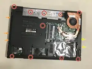
There are a total of 15 screws on the bottom (if I counted correctly)
-
Arrows indicate that I will have another picture attached to show where the indicated screws are.
-
-
-
And now we get to flip it over again!
-
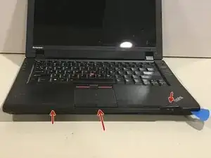
First up is the trackpad assembly area. This is just being held down by plastic clips, so taking an Opener Pick in the crevice should do the job to get it off.
-
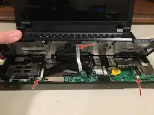
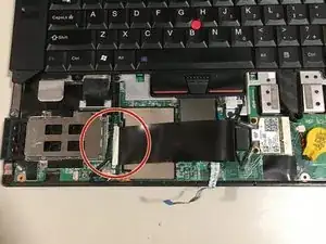
You will also want to disconnect these cables
-
-
-
First, you'll want to disconnect the ribbon cable for the keyboard/trackpad keys
-
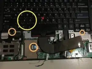
After that, you will want to take off the two screws holding down the keyboard. There is also a ribbon cable hooked up to it that must be disconnected.
-
There is some adhesive under the area marked, so it may take a little more force than usual to lift.
-
-
-
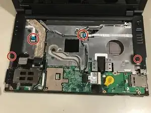
First, disconnect the highlighted cables
-
Next, take them out of their metal clips
-
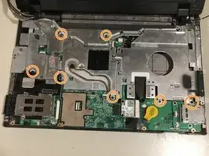
Next, there are 7 screws holding the metal plate in place
-
After that, the metal plate can be lifted right up and out (just be careful to not lose any of the screws when setting it down)
-
-
-
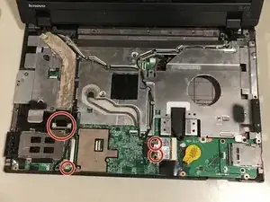
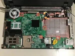
When I got to this step, I only found one screw holding the motherboard, which I found to be extremely odd...
-
I did find threaded holes at the places indicated with a box, so there may be some here.
-
There are also two cables connected here. The one on top of the motherboard being the connector to the rear USB port. The one underneath is the cable that connects to the charging port.
-
-
-
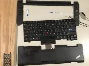
At this point, the only new layout is the shortcut controls, keyboard, and trackpad/wristwrest.
-
-
-
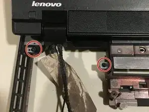
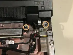
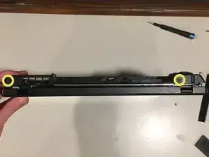
On the left side of the display, there are two screws holding in the left hinge.
-
On the right side, there are also two screws holding in the right hinge
-
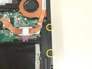
Aaaand behind the laptop there are two screws, one on the right and left side.
-
At this point, the display can be lifted up out of the chassis.
-
-
-
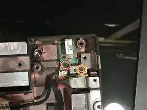
The USB board is easiest to remove first. Take out the screw and lift right up.
-
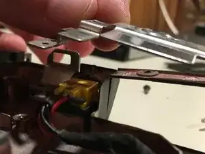
One screw holds the charging port in. The tricky part is the metal holding it in.
-
After removing the screw, you have to kind of lift the metal up to pull the charging port out.
-
-
-
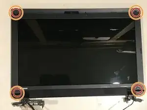
There are three rubber pieces that are stuck on with adhesive that need to be removed. They can be removed with anything small and thin enough to get under them.
-
Under the rubber, there are screws that need to be unscrewed.
-
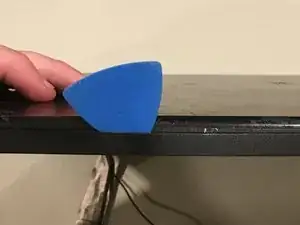
After that, take a opening pick and insert it at an angle shown in the second picture.
-
Repeat the last two steps (three if this one is included) as many times as needed until the bezel is removed.
-
-
-
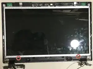
First thing to remove are the speakers. There are two screws holding them in place.
-
Next, I found it easiest to remove the network (wifi) cables. They are easily removed; they just have to be lifted carefully along the lines indicated.
-
-
-
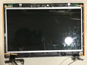
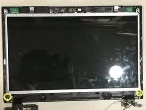
The hinges are connected to a frame that the display is screwed into, so they must be taken out (the display, frame, and hinges will come out in one part). There are two screws (one on each hinge) holding them in
-
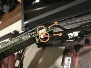
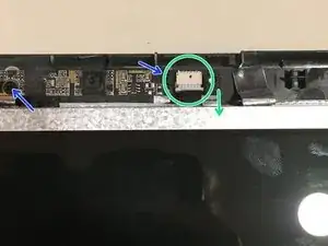
Before lifting the display out, the webcam must be disconnected. Find the connector and pull the cable out in the direction shown.
-
There are also two screws holding the webcam assembly in place
-
At this point, the display can be lifted right out.
-
-
-
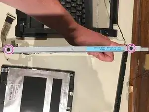
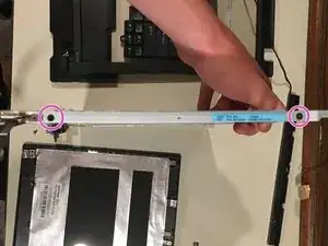
There are two screws on each side of the display panel that connect it to the frame. Unscrew these, and the display will be free.
-
-
-
That's it!
-
Enjoy the laptop you have that is now in pieces!
-
If you feel that you need to reassemble this brick, follow these steps in reverse.
-
Thank you for taking time to read my guide, and have a great day!
-
2 comments
Lenovos are always a pain to gut/repair. Probably because they’re military grade…
Yea it stinks to have to tear one open.
They’re military grade? With my personal experience with a few different models, I wouldn’t think the military would WANT to use them..
