Introduction
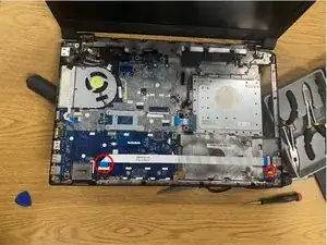
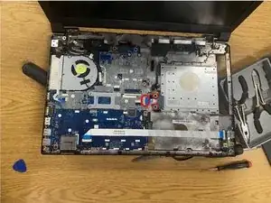
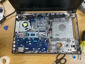
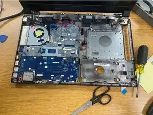
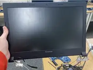
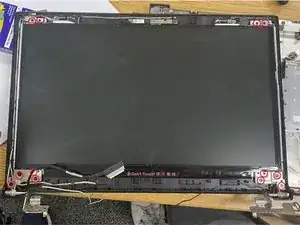
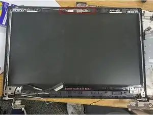
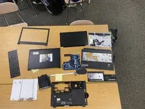
Full teardown of the Lenovo B50-80F0 Laptop.
Created by Students of Cary High School.
Tools
-
-
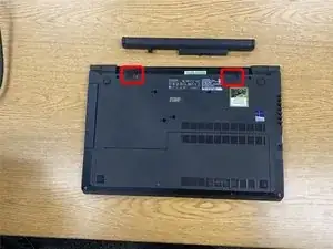
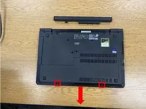
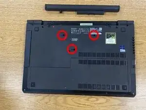
There are two screws (outlined in red) holding the service door in place. Remove these and slide the door off.
-
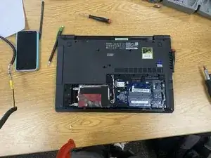
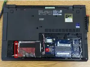
Under the service door, you will see the hard drive, CMOS battery, WiFi card, and RAM.
-
-
-
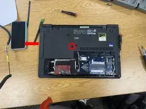
Remove the highlighted screw, then slide the optical drive out.
-
Lower-specced laptops may only have a plastic placeholder for the optical drive.
-
-
-
For the hard drive, remove the highlighted screws and lift and remove the hard drive out.
-
Next, take a plastic spudger, put it under the CMOS battery, and pry it out.
-
Then, pull the sides on the RAM stick(s) and remove them.
-
-
-
The keyboard can be removed from the frame once the three retaining screws (circled in red) have been removed.
-
Once screws have been removed, pop out the keyboard carefully with a spudger and unplug the ribbon cable attaching it to the motherboard.
-
-
-
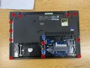
To start, remove the 12 highlighted screws.
-
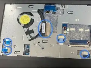
Next, disconnect & unroute the FPC connectors highlighted in blue.
-
Then with a plastic spudger tool, go around the edge of the bezel and pop all the plastic clips.
-
Lift the bezel out.
-
-
-
Disconnect the highlighted flex cable from the motherboard, then peel it up from the casing.
-
Remove the highlighted screw on the right, then simply pull the board and cable out of the system.
-
-
-
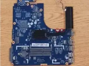
Disconnect the flex cable from the motherboard and then remove the two highlighted screws, and then pull it out.
-
-
-
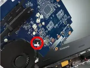
Disconnect the fan cable from the motherboard
-
Remove the one screw that holds the fan in place.
-
-
-
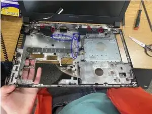
Un-route the speaker cables (highlighted in blue).
-
Remove the retaining screws (circled in red) and pull out the speakers.
-
-
-
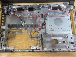
Un-route the antenna cables (highlighted in red)
-
Remove the 6 retaining screws (circled in blue).
-
The display will then be able to be slid out and removed from the rest of the body.
-
-
-
At this point, the display bezel is able to be popped out.
-
Use a thin piece of plastic to wedge it open if necessary.
-
Be careful not to snap the bezel in the process!
-
-
-
Unscrew the 12 retaining screws (circled in red) and carefully pull out the display panel.
-
Be mindful of the connector cable.
-
Flip the display over and remove the connector cable.
-
It should slide out easily.
-
The hinge can also now be removed.
-
-
-
The camera will be at the top of the display.
-
With a plastic tool, carefully pull up the wire on the top.
-
The camera is now able to be popped out.
-
Disconnect the connector cable and remove the camera from the display.
-
