Introduction
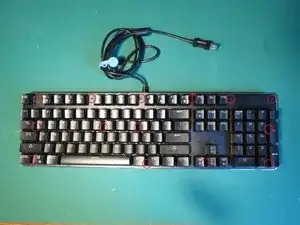
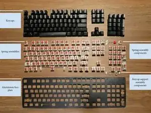
This guide includes a product teardown of a Kogan RGB Mechanical Keyboard and a breakdown of its component's functions, materials, manufacturing methods, dimensions, and weights.
-
-
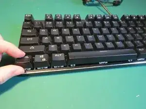
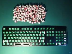
Remove keycaps by pulling directly upwards
-
If removing caps by hand it helps to lever the cap from underneath to loosen
-
-
-
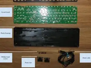
The aluminium face plate is held on with 14 Phillips head screws
-
Use a Philips head screwdriver to carefully remove each screw
-
-
-
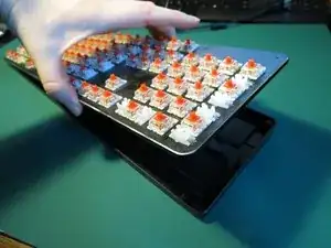
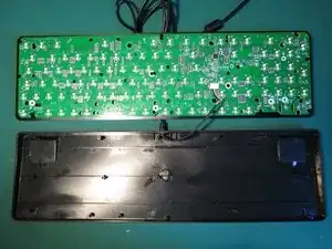
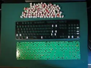
The plastic housing can now be separated from the circuit board and key springs
-
The power cable is still connected so first simply lift the circuit board and key spring assembly up and lay it next to the plastic housing
-
-
-
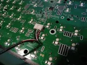
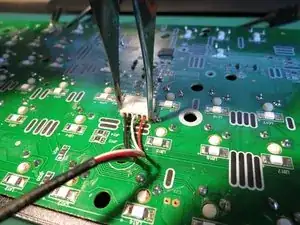
The power cable is secured to the circuit board with a white connector
-
Use tweezers to carefully disconnect the connector
-
-
-
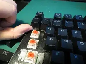
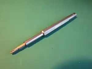
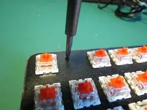
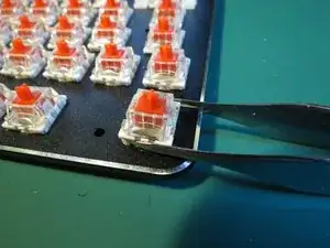
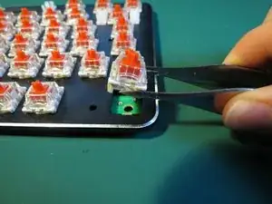
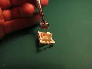
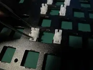
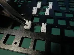
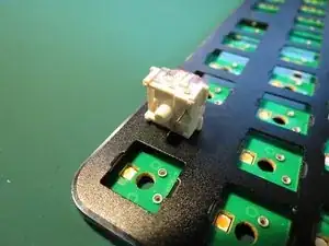
If using tweezers gently locate the tines underneath a spring assembly
-
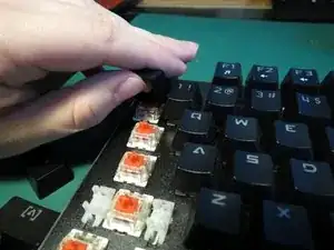
Lever the spring assembly upwards carefully to avoid scratching the aluminium housing or bending the connection pins
-
Aim to pull the spring assembly directly upwards or with minimal misalignment
-
-
-
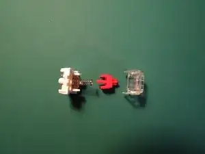
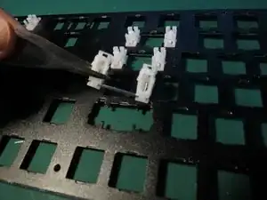
Use a small flathead screwdriver to lift up the clear plastic side until it lifts over the white plastic tab
-
Repeat this for both sides
-
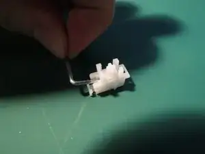
Once both sides are lifted over the white tabs the clear plastic cap can be pulled off
-
This will additionally release the red plastic tab and the spring held within
-
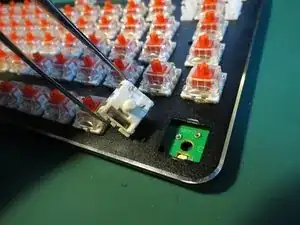
Use tweezers to gently pull the two metal pin pieces directly upwards out of the white plastic housing
-
-
-
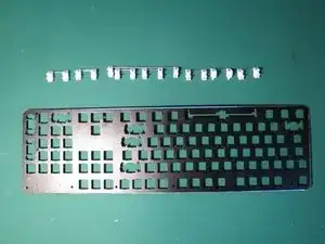
Once all the spring assemblies have been removed from the circuit board the aluminium face plate will be free to lift off the circuit board
-
-
-
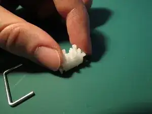
Use tweezers to compress the tab securing the white plastic component
-
Whilst compressing the tab angle the component as shown in order to release it from the aluminium face plate
-
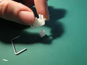
Repeat for the other plastic component
-
Maneuverer the plastic and metal rod assembly out from the aluminium face plate
-
-
-
Pull the metal rod up and out of the plastic piece, this may take some force as the pieces are press fit together
-
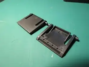
The two plastic pieces on each side can then be separated by simply lifting one off the other
-
-
-
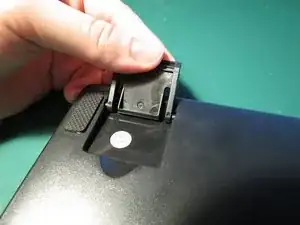
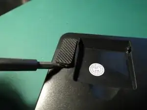
Flip the plastic foot upwards
-
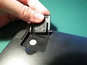
Push the foot towards one side and angle it as shown while applying some force upwards
-
The foot should release with relatively minimal force
-
Repeat for the other foot
-
-
-
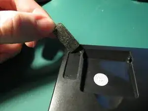
Insert a small flathead screwdriver underneath one corner of the rubber foot
-
lift the foot up and pull off
-
The rubber feet should disconnect with minimal force
-
-
-
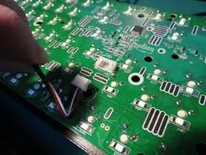
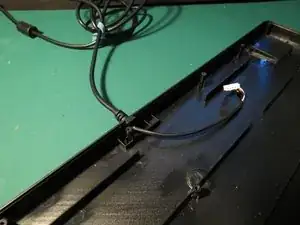
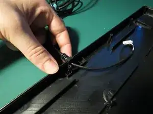
The power cable is simply pressed into the plastic housing without any adhesive
-
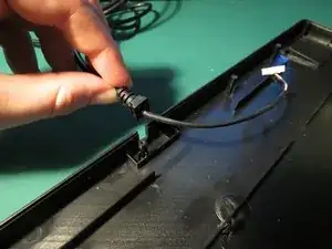
Pull upwards on the cable whilst ensuring the plastic housing is secured
-
The cable should lift out with minimal force required
-
-
-
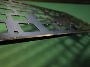
The face plate protects the circuit board from dust and damage. It also provides a unique aesthetic quality through the chrome bezel.
-
The plate was cut and pressed from aluminium sheet metal then powder coated black.
-
Dimensions: 435x127x4 mm. Weight: 162g
-
-
-
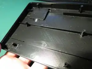
The base is comprised of three main components, the plastic base, plastic feet, and rubber feet. These components work together to provide protection to the circuit board, support for the keys, and an aesthetic quality to the product.
-
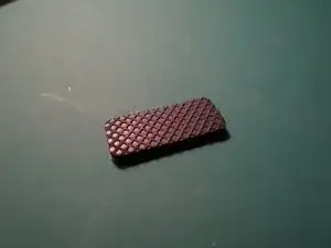
The plastic base and feet are black injection moulded ABS and the rubber feet are moulded and stamped silicone.
-
Plastic base | Dimensions: 433x125x15 mm Weight: 162g
-
Plastic feet | Dimensions: 30x40x5 mm Weight: 1 g
-
Rubber feet | Dimensions: 25x10x2 mm Weight: <1g
-
-
-
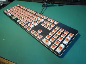
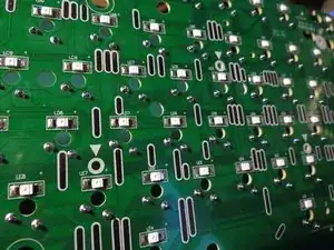
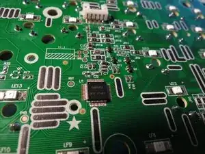
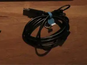
The electrical system is comprised of the circuit board and power cable
-
The circuit board connects to the computer and keys, processes inputs and sends outputs. The power cable provides power to the product by USB connection to a computer.
-
-
-
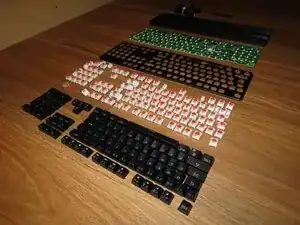
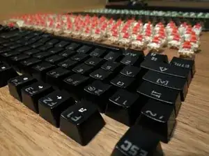
The keycaps provide the tactile surface for users and allows light to shine though to aid in labelling keys.
-
The keycaps are made by double-shot injection moulding ABS to combine two colours of plastic together. This is done to permanently provide a label for each key and let the RGB light shine through.
-
Dimensions: 130x12x12 mm max. Weight: 4g max.
-
-
-
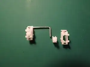
The key supports provide support at each end of longer keys to avoid excess wobbling. This assembly includes the spring rod and two plastic connection components at each end. The inner plastic components fit into the keycaps whilst the outer components create a supportive structure.
-
The metal rod is made from extruded and bent steel. The plastic components are injection moulded ABS.
-
Metal rod | Dimensions: 25x11x2 mm Weight: <1g
-
Plastic components | Dimensions: 20x20x10 mm Weight: <1g
-
-
-
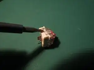
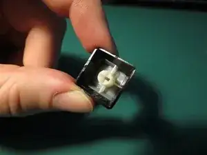
The key springs create electrical connection to circuit board. Additionally providing a spring to allow keycaps return to their upwards position.
-
This assembly is comprised of the plastic housing, plastic connector, spring, and two electrical pins.
-
Overall dimensions: 13x15x20 mm Weight: <1g
-
As the weight for this assembly is less than 1g the components weights will not be listed in the following sections.
-
-
-
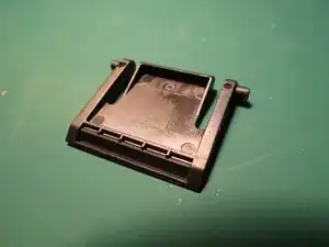
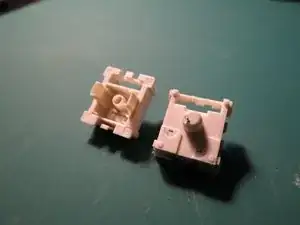
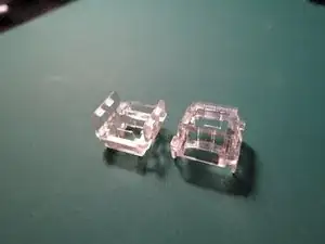
The housing assembly protects and holds together other key spring components. The lower white component locates the circuit pins and spring to the correct positions. The upper clear component clips onto the white lower housing and secures the keycap connector.
-
Both components are injection moulded however to achieve the clear finish the upper component is manufactured from acrylic whereas the lower opaque component is ABS.
-
Upper component | Dimensions: 13x15x10 mm
-
Lower component | Dimensions: 13x15x13
-
-
-
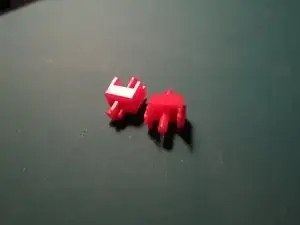
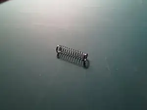
The keycap connector and spring work together to attach the keycap to the spring assembly and push the keys to the upwards position once pressed down. Additionally the red key connector pushes against the larger electrical pin which opens the electrical circuit, sending a signal to the circuit board that the key has been pressed.
-
The keycap connector is injection moulded red ABS. The spring is thinly extruded and coiled steel. Finally, the pins are stamped, pressed, and bent from copper sheet. These components all fit within the spring housing.
-
Keycap connector | Dimensions: 13x7x9 mm
-
Spring | 15x4x4 mm
-
Large pin | 23x10x0.1 mm
-
Small pin | 10x10x0.1 mm
-
-
-
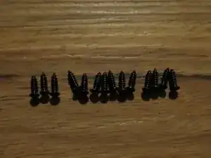
The face plate is fastened to the plastic base by 14 M3 x 18mm Phillips Flat Head Carbon Steel Wood Screws.
-