Introduction
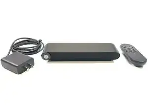
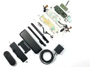
A look inside the Facebook Portal TV.
-
-
Features:
-
Smart Camera and Smart Sound
-
Alexa Built-in
-
Easy to Disable Camera and to Disable Microphone with push of button or blocking camera lens
-
Video Calling via Facebook, and Messenger
-
120 Degrees Field of View
-
12.5MP Camera Resolution
-
Far-field 8-Microphone Array
-
-
-
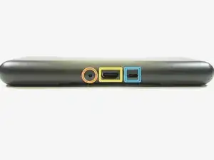
View of the product from the outside
-
Power connector
-
HDMI Output
-
USB C Interface
-
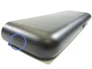
Button to disable Microphone and Camera
-
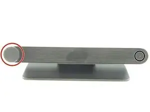
Camera Cover Slide
-
System LED
-
-
-
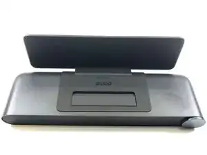
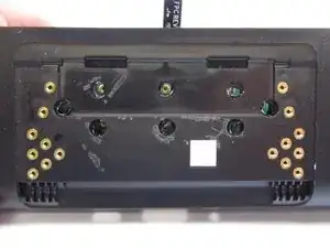
At first there didn't seem to be way into this device
-
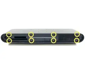
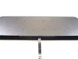
Flipping the device upside down, there was cover between the enclosure, and the base. Removing this cover revealed sixteen T5 screws
-
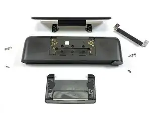
Removing the sixteen screws, only removed the base
-
There was still no obvious way into to the product
-
-
-
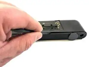
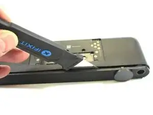
It was time to get the Spudger Tool out and test a few edges
-
Working along the front edge, it appeared that the face plate was glued or held in place with double stick tape
-
The Spudger Tool was use to loosen a gap along the face plate edge
-
A Jimmy Tool was used to further release face plate
-
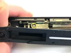
With the face plate removed
-
we can see the led light pipe
-
we can also see the camera shut off switch
-
LED Light Pipe
-
-
-
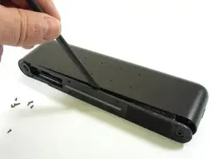
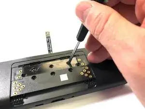
At this point we close to getting into this device
-
Now we are confronted with eight more T5 Screws
-
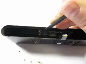
Time to get the Spudger Tool out and pry along the face again
-
This face plate houses the camera and speaker
-
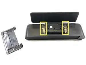
With the face plate pulled back, we are confronted with two more T5 screws in the very back of the unit on the left and right of the product
-
-
-
We are much closer now to opening up the unit and getting access to the electronics inside
-
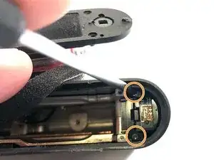
As mentioned in the last step, there are two T5 screws in the back of the unit
-
Just when we thought we had all the screws removed, the switch on the side unit is stopping the electronics from being pulled out of the enclosure. It has two T2 screws holding it in place
-
-
-
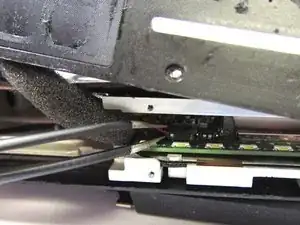
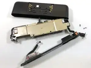
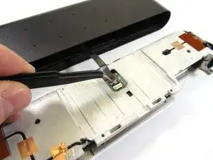
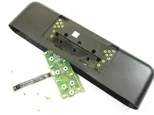
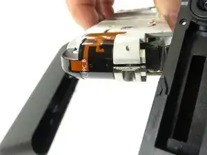
We can now use tweezers to remove the speaker cable attaching the front panel to the rest of the enclosure.
-
Then we can slide out the metal enclosure that holds the electronics from the main enclosure
-
Now use we can use tweezers to flip up the flex cable lock latch to release the flex cable attached to the main electronics in the metal enclosure and outer body. As will be seen shortly, this cable goes to a microphone array PCB in top of the outer enclosure
-
-
-
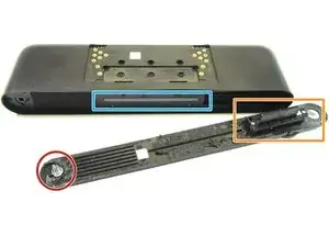
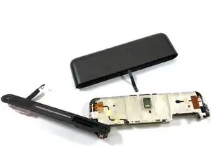
Now with the outer enclosure removed, and the front plate removed we can work on opening up the metal enclosure that contains the main electronics
-
The metal enclosure is held together with eight T5 screws. Use a T5 tool to remove these screws
-
The metal enclosure is also held together on each outer end with a flexible sticker type antenna. These flexible antenna will have to be removed before the metal enclosure can be opened up
-
-
-
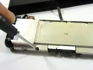
Unfortunately, removing the flexible antennas will destroy them. Since the antenna are flexible, and have adhesive use to hold them in place. However, It may be possible to remove the antennas and use some adhesive to hold them in place when putting the unit back together
-
Use tweezers to remove the flexible antennas on each end of the metal enclosure
-
-
-
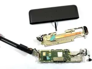
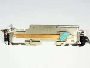
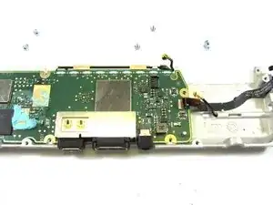
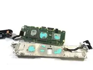
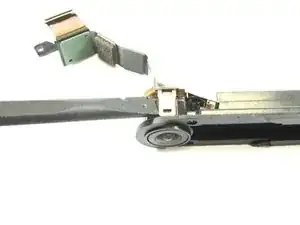
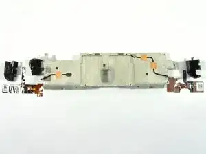
With the metal enclosure screws removed, and the flexible antennas removed from each side of the metal enclosure, the metal enclosure can be opened to give us the first look at the electronics within
-
We also see that the metal enclosure is not meant for much RF Shielding as much as it is meant for cooling and weighting down the product.
-
The cooling is via a copper heat pipe
-
-
-
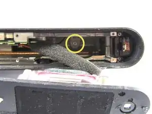
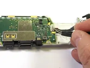
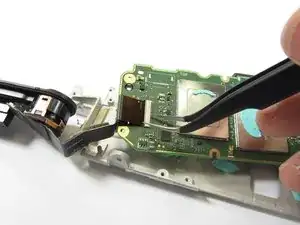
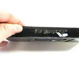
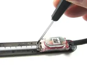
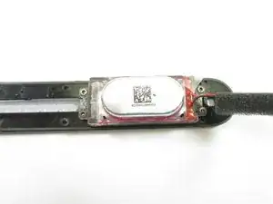
Now it is a good time to remove the side button flex cable from the bottom side of the unit.
-
This can be done by using tweezers to remove the plastic film over the button connector. Then using tweezers to lift up the connector latch and to pull the button flex cable free
-
-
-
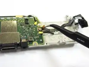
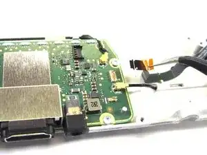
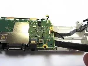
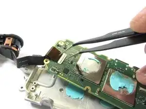
Before we can get a closer look at the electronics, we also need to remove the u.fl Antenna cables that attached to the main electronics board
-
A Spudger Tool can be used to pry up and off the Antenna cables from u.fl connectors
-
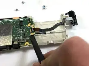
Now use a Spudger Tool to remove the main electronics board from the metal enclosure
-
-
-
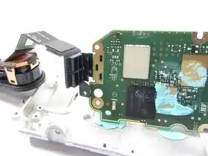
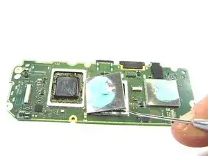
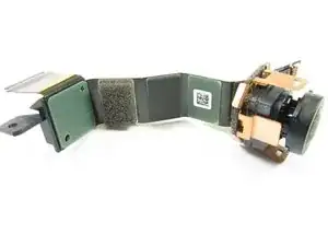
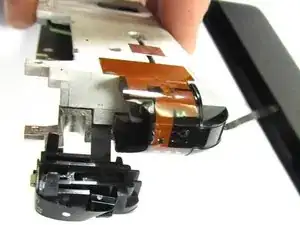
With the main electronics board removed, we can now remove the camera that is attached
-
To do this, first remove the plastic film over the camera connector. Then remove camera flex cable by prying up on the connector latch and siding out the camera flex cable free with tweezers
-
-
-
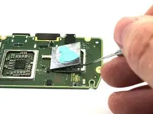
Camera flex cable is also held in place via a thick plastic block attached to the main electronics PCB. This plastic block can be pulled away from the PCB
-
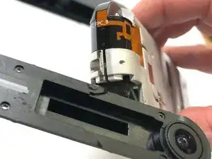
Now that we have the main electronics PCB removed, we turn our attention back to the small electronic PCB locate in the top of the main enclosure
-
-
-
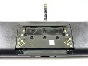
As can be seen in the first step photos of this teardown, there are eight pin holes in the top of the main enclosure. These pin holes are for the microphone array. The holes pass sound to the eight MEMS Micrphones below the pin holes
-
On the opposite out side of the main enclosure, we see eight circle holes. These hole are covered on the inside by black tape
-
-
-
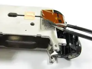
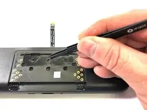
We can use tweezers to punch a holes in the black tape to give access to the screws that hold the microphone array PCB on the opposite side of the enclosure
-
Once we have holes punched in the tape we use a T2 Tool to remove the screws holding the Microphone PCB in enclosure
-
-
-
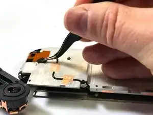
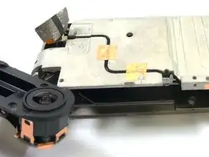
After the microphone array PCB mounting screws have been removed, we can just Spudger Tool to pry the PCB free. It is also held in place with double stick tape in addition to the screws
-
Once the Microphone Array board has been removed, we can get a closer look at it
-
-
-
Now we can turn our attention to separating the camera from the front panel cover
-
Use a Spudger Tool to remove pry up on the metal tab attaching the camera to the front cover
-
-
-
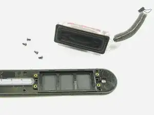
Now we can separate the Speaker from the front cover
-
The speaker is held in place with four T2 Screws. Use a T2 Tool to remove these screws
-
-
-
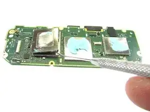
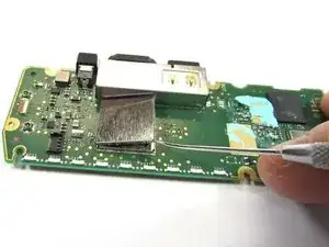
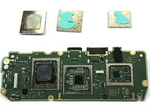
Turning our attention back to the main electronics PCB, we need to remove the RF Shielding so we can see components under the RF Shields
-
Use a pick tool to remove each RF Shield. The RF shields are only snapped in place and can be easily removed
-
-
-
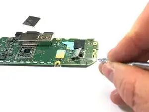
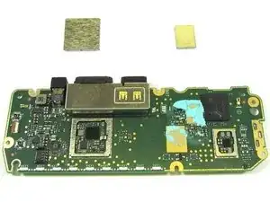
Now flip the main electronics board over and remove two more RF Shields
-
Use a dental pick tool to remove these RF Shields
-
-
-
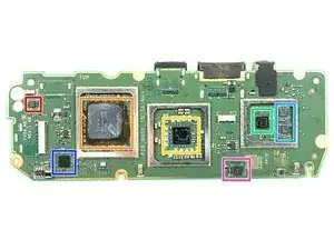
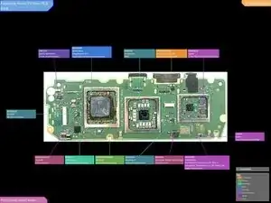
With the RF Shielding removed, we can take a closer look at the components on the PCB. The main SoC is underneath the Sk Hynix Memory, and not easy to access. Sk Hynix also makes image processors, so it could be their SoC/Imager. A number of parts could not be crossed referenced, if you have information on a part please leave it in the comments
-
FLH - could not cross reference
-
DSP Group D7A1C Audio DSP
-
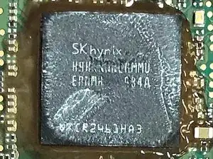
Sk hynix H9Hknnncrmmuernmh LPDDR4 32GB 256Mx16 PC3733
-
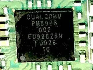
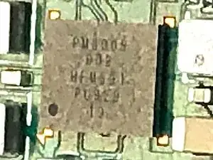
Qualcom PM8998 Power Management IC (PMIC)
-
Qualcom WCN3990 - WiFi 2.4Ghz, 5Ghz, 2x2, Dual-band concurrent, 802.11ac
-
Qualcom 3C/485Z - could not cross, but may be Power Amplifiers for WiFi
-
AW9109 - could not cross, but may be an LED driver IC from Shanghai Awinic Technology
-
-
-
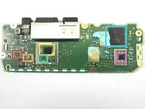
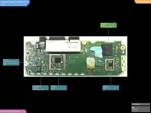
With the RF Shielding removed from the backside, we can take a closer look at the electronics on this side of the PCB. Also, a number of parts could not be crossed, so if you have information on a part please leave in the comments
-
8mB / +19C / 10 - could not cross reference
-
894A / A1 12 / +9228 - could not cross
-
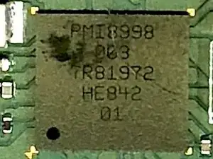
Qualcom PMI8998 - Power Management IC. Used with PM8998 (other side of the PCB)
-
Sinopower - SM3337 - P-Channel MOFET
-
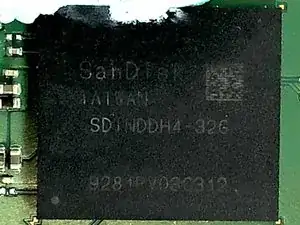
SanDisk Embedded 32GB Flash Disk
-
Qualcom PM8005 Power Management IC
-
-
-
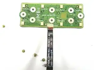
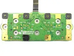
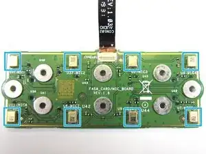
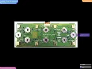
Now we turn our attention to the microphone array board
-
We can see that one side of the board has ports (holes) for the microphones
-
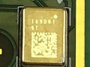
The other side of the board has the eight MEMs Micophones
-
Infineon IM69D130 MEMS Microphone
-
-
-
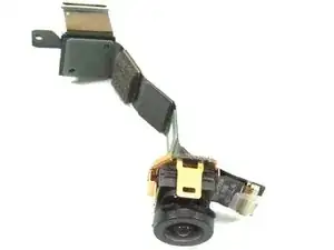
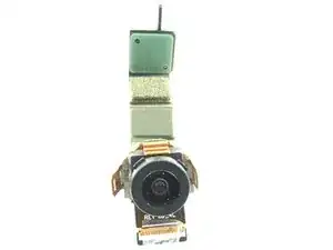
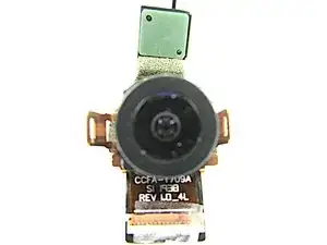
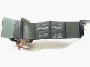
Now let us review the camera in the unit. The camera lens and imager are combine and not easily separated.
-
The Camera could not be crossed reference with the marking on the camera flex cable. There are no markings on the camera body.
-
-
-
Next, let us review the speaker
-
Speaker part number - 8GVRMS138N9454 - could not cross reference
-
-
-
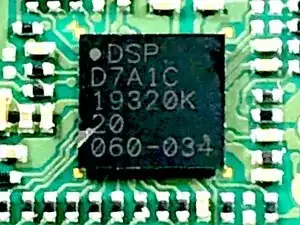
Close view of some of the components
-
DSP Group D7A1C Audio DSP
-
SanDisk Embedded 32GB Flash Disk
-
As mention earlier the SK hynix DRAM is bonded over the main SoC
-
-
-
More component close up views
-
Qualcom PM8998 Power Management IC (PMIC)
-
Qualcom PMI8998 - Power Management IC. Used with PM8998 (other side of the PCB)New line.
-
Qualcom PM8005 Power Management IC
-
-
-
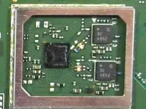
Qualcom WCN3990 - WiFi 2.4Ghz, 5Ghz, 2x2, Dual-band concurrent, 802.11ac, and Qualcom 3C 485Z - possible Power Amplifiers for WiFi Radio
-


8 comments
I suppose first gen 10 inch FB Portal also has WCN3990 2x2 MIMO antennas?
That's a beautiful processor
Step 5 has a mistake.
I assume the author meant to say, 8 t2 scews (where they said t5) - as the required tool list has a t2 listed… However, my portal tv had 8 t3 screws here, NOT t2!