Introduction
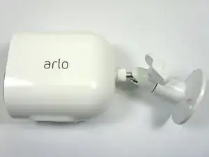
A look inside the Arlo Ultra 2 Security Camera.
-
-
Features:
-
4K Video with HDR
-
Color Night Vision
-
Integrated Spotlight
-
180° Viewing Angle
-
Crystal Clear 2-Way Audio
-
Weather Resistant
-
Advanced SmartHub
-
-
-
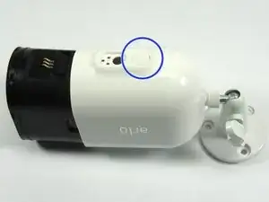
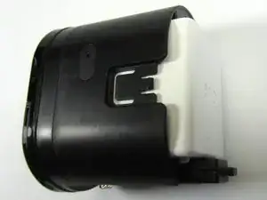
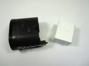
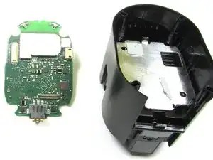
To open the Arlo Ultra Camera, press the Button on the bottom, and pull Camera Face (Camera Body) away from the Camera Enclosure
-
Set the Camera Enclosure to the side. It will not be needed for the rest of the Teardown
-
-
-
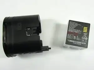
Remove the Battery from the Camera Body by gently pulling the Battery away from the Camera Body
-
The Battery Capacity is 4800mAh
-
-
-
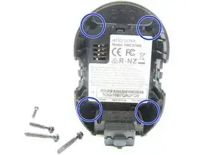
To remove the Camera Face Plate from the Camera Body, remove the four PH00 screws in the Battery Compartment Area that secure the Camera Face Plate to the Camera Body
-
Use the Spudger Tool to pop off the Camera Faceplate
-
-
-
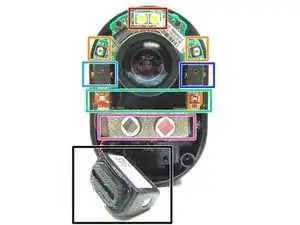
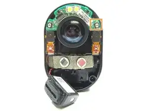
With the camera face plate removed, we get our first look at some of the components that make up the Arlo Ultra Security Camera
-
Spot Light LEDs (400 lumens)
-
Infrared Light LEDS
-
-
TDK ICS-41350 Microphone
-
Left Side, Light Detector. Right Side, Multi-Color LED
-
-
Speaker / Siren - NG521-0015-01B18100010711
-
-
-
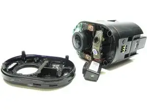
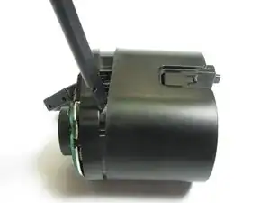
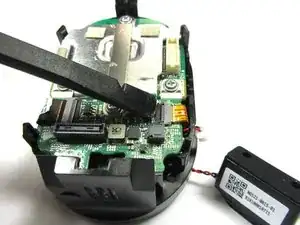
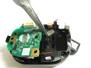
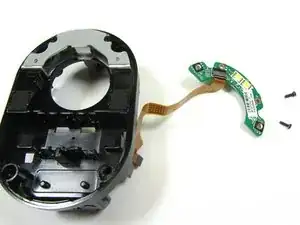
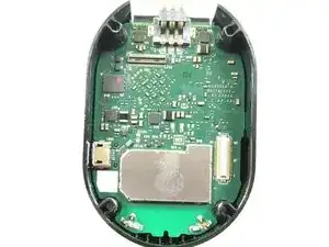
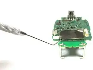
With the Camera Face Plate removed, use the Spudger Tool to pry the Camera Assembly away from the Camera Body
-
Once the Camera Assembly comes loose from the Camera Body, use the Spudger Tool to pry against the two plastic tabs on the bottom of the Camera Assembly that hold the Camera Assembly to the Camera Body PCB (Main PCB)
-
Pull the Camera Assembly away from the Assembly Body
-
The Camera Assembly is held in place by Zero Insertion Force Connectors to the Main PCB in the Camera Body
-
-
-
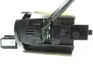
With the Spudger Tool, pry off the cable to the Speaker / Siren from the Speaker Connector
-
With the Spudger Tool, release the Flex Cables attached to the Small PCB on the back of the Camera Assembly
-
-
-
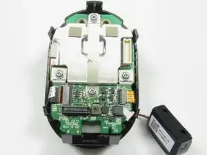
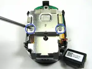
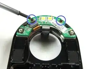
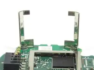
With the Flex Cables released from the Small PCB on the back of the Camera Assembly, remove the two PH00 screws that hold the Metal Bracket in place
-
Use the Spudger Tool to pop off the Metal Bracket
-
-
-
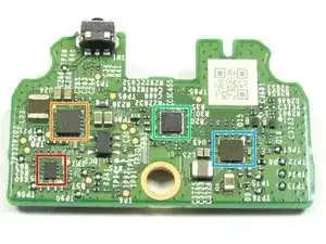
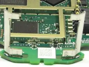
Now that the Small PCB has been removed, we can review the components on the PCB. Some parts could not be crossed referenced. Please leave a comment if you happen to know a part or parts.
-
Small PCB Topside
-
U1 Part Markings: 3070, TI 861, AXLY
-
Small PCB Backside
-
U24 Part Markings: PA81, TI 686, A6KS
-
-
U5 Part Markings: 18M
-
-
-
-
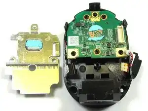
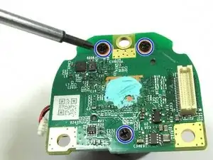
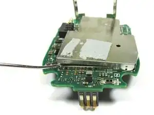
Remove the Large EMI / Heatsink Shield from the back of the Camera Assembly by removing the two PH00 Screws
-
Pry off the Large EMI / Heatsink Shield from the Camera Assemble using the Spudger Tool
-
-
-
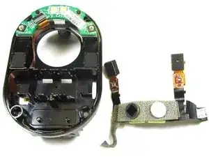
With the Large EMI / Heatsink Shield removed, we can now remove the Flex PCB that contains the Microphones, Light Detector, Multi-Color LED and PIR Sensor
-
Use a pair of Long Needle Nose Pliers to pull the Metal Shield Tape from the backside of the Camera Assemble Body.
-
From the frontside of the Camera Assembly Body, pull the Metal Shielding Tape through the hole to the backside of the Camera Assembly Body
-
Use the Spudger Tool to gently pry out the Flex PCB. The Flex PCB is held in place by double stick foam tape
-
The Speaker / Siren can also be removed after the Metal Shield Tape has been removed by pulling the speaker cable through the hole between the backside and frontside of the Camera Assembly Body that was occupied by the Metal Shield Tape
-
-
-
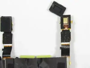
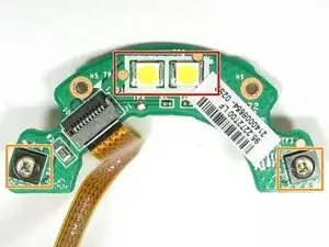
With the Metal Shield Tape removed and the Foam Tape scraped off, the components on Flex PCB can be reviewed
-
-
TDK ICS-41350 Microphone
-
Light Detector
-
Multi-Color LED
-
-
The Flex PCB has foam tape on both sides, and a Rubber Cavity Cap that surrounds each Microphone. The Foam Tape, and Rubber Cavity Caps can be removed to allow a close up view of the Microphones
-
-
-
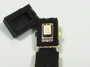
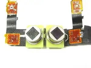
Frontside and Backside Close up Views of the Right Side Microphone on the Flex PCB
-
-
-
-
Frontside and Backside Close up Views of the Left Side Microphone on the Flex PCB
-
TDK ICS-41350 Microphone
-
-
-
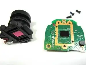
After the Flex PCB has been removed, the Camera Lens plus Image Sensor PCB can be gently pulled out from the Camera Assembly Body
-
-
-
Use the PH00 Tool, to remove the the two screws holding the the Spot Light LEDs and Infrared Light LEDs PCB to the Camera Assembly Body
-
Close up view of the Spot Light LEDs, and Infrared Light LEDs
-
Spot Light (400 Lumens)
-
Infrared Light LEDs
-
-
-
Use the Spudger Tool to release the Camera's Mechanical Focus Motor Control Cable
-
Use the PH00 Tool to remove the three screws holding the Camera Lens to the Image Sensor PCB
-
-
-
Close Up View of the 4K Image Sensor PCB. The Image Sensor has no part number that could be cross referenced. Leave a comment, if you know the part number of the Image Sensor.
-
Close Up View of the backside of the Image Sensor PCB
-
U4 Part Markings: PA81, TI 878, A5X3
-
Please leave a comment if you know the part number for U4
-
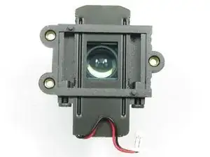
Close Up View of the Camera Lens
-
-
-
The Small EMI/Heatsink Shield is not soldered on and can be easily removed with a Dental Pick Tool
-
Use the Dental Pick Tool to pry up the sides of the EMI/Heatsink Shield
-
Once the EMI/Heatsink Shield has been loosen, it can easily be pulled off the rest of the way
-
-
-
The Large EMI/Heatsink Shield is not soldered on and can be easily removed with a Dental Pick Tool
-
Use the Dental Pick Tool to pry up the sides of the EMI/Heatsink Shield
-
Once the EMI/Heatsink Shield has been loosen, it can easily be pulled off the rest of the way
-
-
-
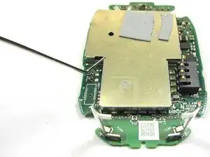
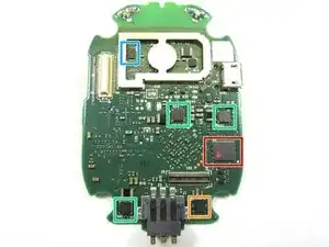
Main PCB Front Side Close Up View. Please leave a comment if you know information about U5, U41,U37,U24, U32
-
-
U5 Part Marking: 1200, P68, AC5F
-
U41, U37, U24 Part Markings: PA81, TI 878, A5X2
-
U32 Part Marking: GT, 43, 828
-
-
-
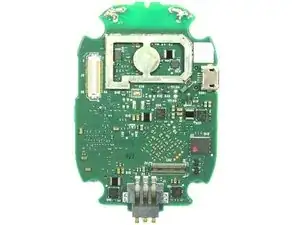
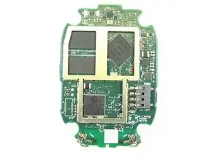
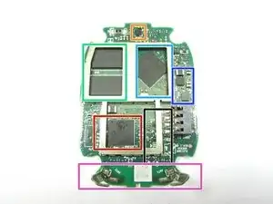
Main PCB Backside Close Up View. Please leave a comment if you know information about U1, U26, and U42
-
-
-
U1 Part Markings: OA00805-B56G, TIVH62. Appears to be the video image processor
-
U7 - Cypress Ultra-Low Power, 802.11a/b/g/n WiFi/BLuetooth 5.0 Controller
-
U26, and U42 Part Markings: PA61, TI 871, A241, and 851DD, TI 838, A827
-
RF Front end with RF Switches, RF Bandpass Filter, and possible a RF PA
-
Dual WiF / Bluetooth Antennas
-


7 comments
I would like to know if its possible to buy the camera lens, anyone know?
I also need a lens. I have one camera that broke a lens when it fell.
Stephen -
Even I also have the same question regarding the camera lens.I have another query to add on that I have two Arlo Ultra home security cameras.
I have purchased them for a couple years ago.I am facing an issue concurrently about the “Arlo Camera Offline Error”.I have tried out all the manuals as directed arlo security camera review .Guide us what we have missed out?
I also have a camera that shows offline after the battery died. I can’t get it to reconnect even with other batteries. It won’t charge a battery and there is no LED activity either.
Stephen -
See last two comments. I had two cameras with different issues so I thought I would swap the lens across. The one with the broken lens is also offline now. So still no solution.
Also the Arlo online support has not been responding even when I’m logged in. So not sure what the warranty is worth.
Stephen -