Introduction

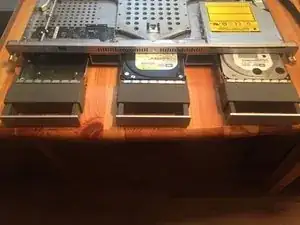
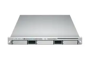
A quick step by step guide to full dissemble a 2006 Xserve Apple Server

  1. Tj1L5uP4GiVUdwNV
    • Unplug power and connections and hold power for 15s to make sure the residual power is gone

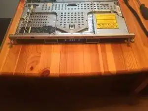
    • Careful with the fibre lines if you have a raid attached

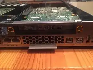
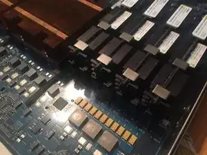
    • Graphic card if installed

  2. miSmuiukuIkLONMY
    miSmuiukuIkLONMY
    mgYSwmIGfBfxBeCN
    mak3hnYCX1pGrAuc
    • Unscrew the two thumb screws at the back.

    • Pull back on the top, then remove the top cover.

    Can’t seem to get the cover off my x serve i’ve undone the screws at the back but it doesn't seem to want to budge?

    sambetsy -

    Pull on the thumb screws strait back it will un hook after a short distance then lift straight off

    mitch -

    Frankly, this is the hardest part of the "take-apart". Because of the age of these things, the cover gets stuck. It happens. A couple of things to check for,

    1. Make sure the "Allen" key lock at the front is set to the "Unlock" position. Otherwise, this will prevent the cover from being removed.

    2. If the cover is really stuck, (has happened to me more than once), use a LARGE flat bladed screwdriver and GENTLY pry the back of the cover, at the rear, and at the front, so that the cover SLIDES back. It will slide back approx. 3/8", and then you can lift it up. When you replace it, if you anticipate doing this often, you might consider applying a very, very thin layer of lithium grease to the areas that bind, so that the cover isn't so hard to remove the next time.

    ECJohansen -

  3. oNNuA2LYYrAIPp2X
    oNNuA2LYYrAIPp2X
    1CLJyoA6IcauOVQI
    eLLpQYpSyR6sv1ec
    • pull out and to the right with the black locking lever

    • Pull out module

  4. Y4ogYtpY5epIhHSO
    Y4ogYtpY5epIhHSO
    XEVK4Z4UJoUxft6D
    XjkQ6mfrKZkDtYvk
    • Push on the caddy handles to release the handle's then pull each one out.

  5. gkWMIeUBb6c6YCo2
    gkWMIeUBb6c6YCo2
    6KFrBRZDBR6W5K2g
    wnuqNVQ1Vv32MhyY
    • use a #1 phillips on the 5 screws holding the Airduct in place.

    • slide up and out easily.

    • carefull with the backplane-to-logic board I/O cable

  6. NSpmcWMYVPrvIpTt
    NSpmcWMYVPrvIpTt
    sfhrGToDAxp2uSZZ
    LtScDMIFxeFan6Xb
    • please note these are captive thumb screws and will not come all the way out

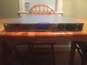
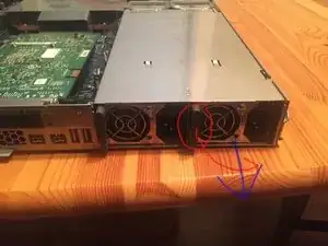
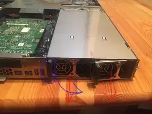
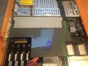
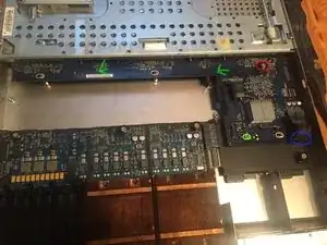
    • To remove the fan array you need to loosen two phillips on the right and left of the array as noted in the pic's.

    • Carefull around the fan plug requires you to pull straight up after screws are lose

  7. KEKUIctIbQEiiIrW
    KEKUIctIbQEiiIrW
    5pPPqnhxWktiUstX
    fLnkVFWrECgnbMmZ
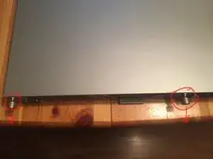
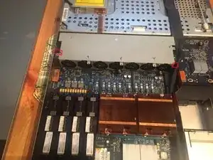
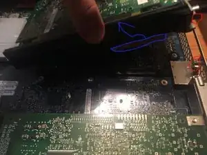
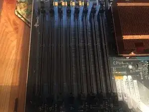
    • Loosen the two captive screws that secure the riser bracket to the back panel.

    • pull up a little to clear the captive screws then lean back should come out easy

    • the Screws in the case act like alinement pins careful when pulling up

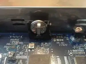
    • Also a good time to check the ROM battery! Replace battery only with type CR2032.

  8. rrMHiwYWyNIuwxdG
    rrMHiwYWyNIuwxdG
    PR4niueZSFaSFGBD
    JY6SeJPOqVQ4v4AI
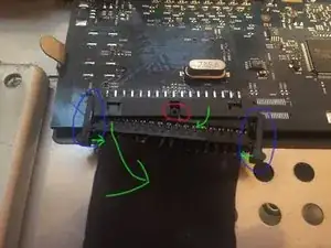
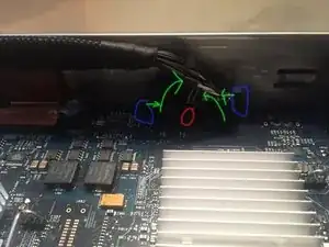
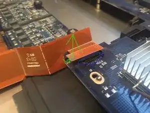
    • This is a delicate cable push the 2 sides together to release

    • This cable is molded to go back in only one way do not try any other orientation

    • Pop one side out then rock the connector wile pressing on the other tab for easier removal

    • The connecter is keyed for one way only

  9. KQyMFcbAap5wTouP
    KQyMFcbAap5wTouP
    4F1HQrM1Gp2hDv2n
    4reyBZEKQxufKQCJ
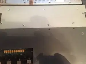
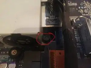
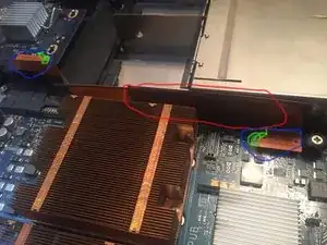
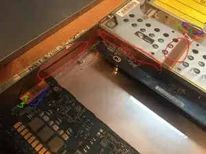
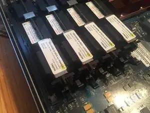
    • they are only press in connectors use a Spudger to pry one side, should come free after a little force

    • Carefull with the connecters as they can be damaged!

    • Note! there is adhesive on the side of the cable along the power module's side

  10. XZABjS2drYFUwjWB
    XZABjS2drYFUwjWB
    ddJftRFbvqaNKCbD
    nTxJlOsw12GGjlaS
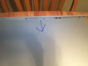
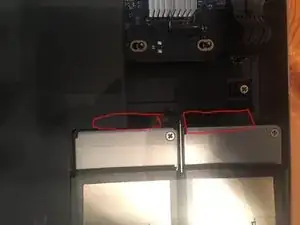
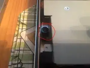
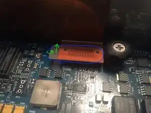
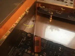
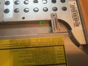
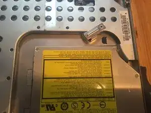
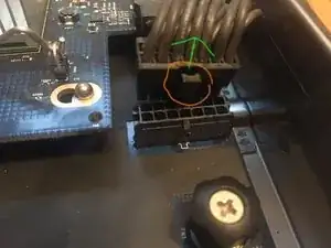
    • lift one side of the connector gently it should pop out

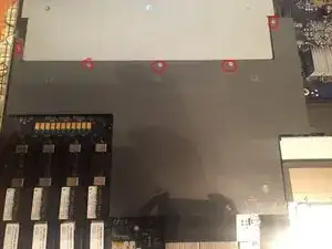
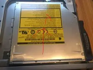
    • !Note! more adhesive out lined in red!

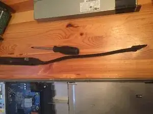
    • Don't Use a screw driver like i did use a plastic Heavy-Duty Spudger

  11. lGVu2xOMcD2FoHBG
    lGVu2xOMcD2FoHBG
    b4PoqJVGwMJxODMv
    WApaxGlWpwvHDTfA
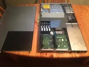
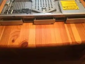
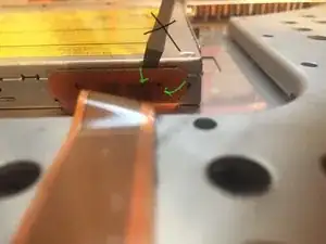
    • Unlock the CD locking leaver by sliding the arm to the left.

    • Push back away from bezel then lift up and out the drive.

    • Unscrew 4 #0 Phillips screws and remove carriage

  12. hevuyDQldCOiskjg
    hevuyDQldCOiskjg
    tgu6fbNKiWPJUka6
    u23TIXAlEQIPer6M
    • To remove open the tabs on either side of the Ram slot to remove~ repeat for all ram.

    • !note! Max Ram on a 2006 =32GB

  13. lVXMhpgPjhsmTX5j
    lVXMhpgPjhsmTX5j
    tfTOgQUyAfdGIw2p
    • Unscrew the one thumb screw on the main part of the board

mitch

Member since: 09/07/16

262 Reputation

0 comments