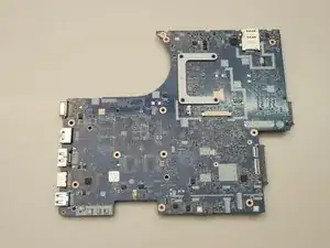
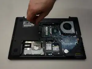
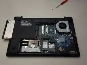
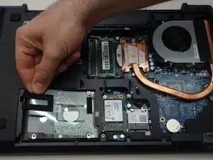
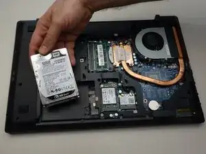
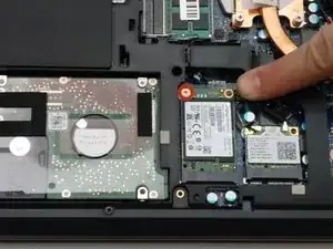
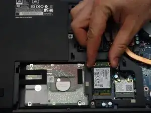
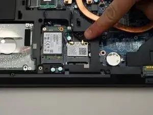
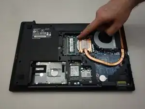
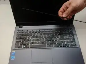
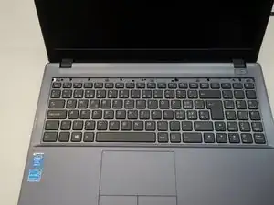
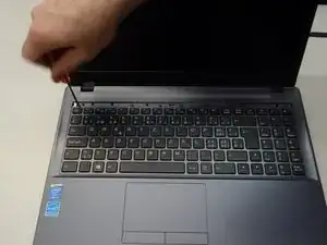
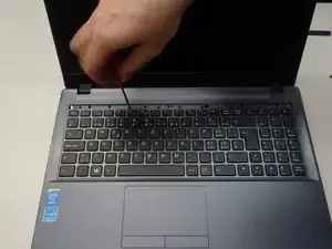
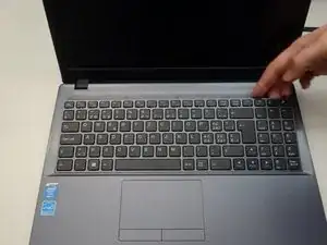
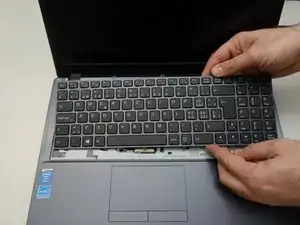
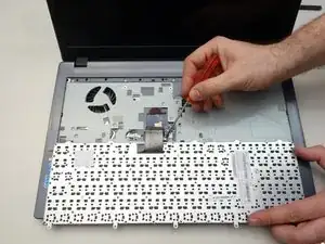
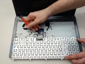
Introduction
Tools
Parts
-
-
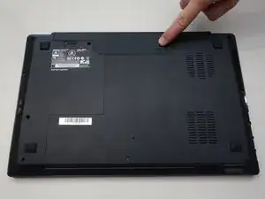
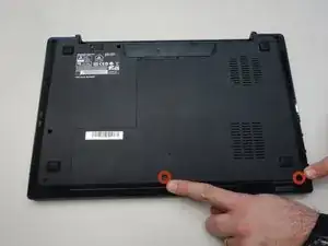
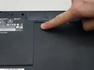
Slide the latch on the right to the unlocked position.
-
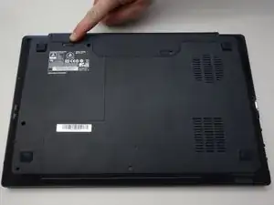
Slide the latch on the left to the unlocked position.
-
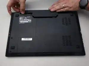
Remove the battery pack from the slot.
-
-
-
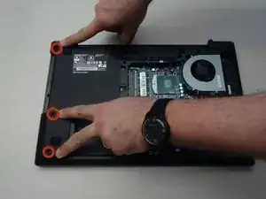
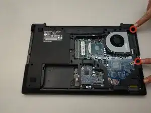
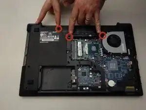
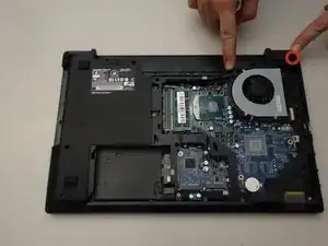
With your #0 Philips screwdriver remove the 2 screws from the bottom panel.
-
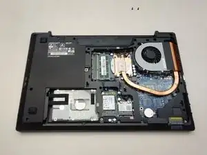
Now you can remove the bottom cover.
-
-
-
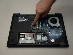
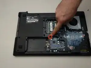
Locate the screw securing the CD/DVD drive.
-
Remove the Phillips screw securing the drive.
-
Remove the CD/DVD drive by simply sliding it out from the chassis.
-
-
-
Lift out the plastic tab (including the rubber part that holds the HDD in its slot).
-
Slide the drive to the left to disengage the connector then lift to remove the HDD from its SATA3 port.
-
-
-
Using a Philips screwdriver #0, remove the screw securing the SSD.
-
Lift the end of the SSD slightly and pull it straight out to remove it.
-
-
-
Carefully unplug the MAIN and AUX antennas.
-
Remove the retaining screw with a Phillips #0 screwdriver.
-
Lift the chipset slightly and remove it from the connector.
-
-
-
Locate and separate the blade springs that hold the memory module in place.
-
Remove the memory module (RAM).
-
-
-
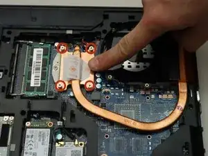
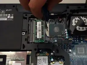
Using a Phillips screwdriver, unscrew the four captive screws securing the heatsink to the motherboard.
-
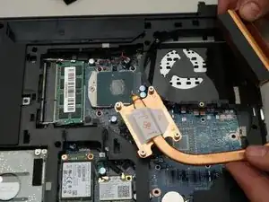
Remove the heatsink.
-
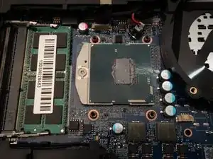
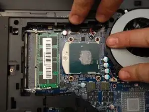
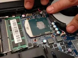
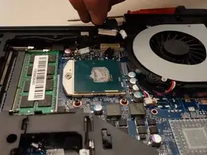
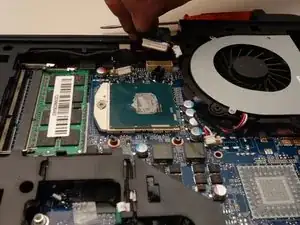
The processor and its retention mechanism are now visible.
-
-
-
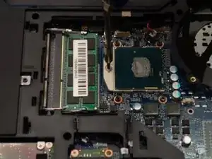
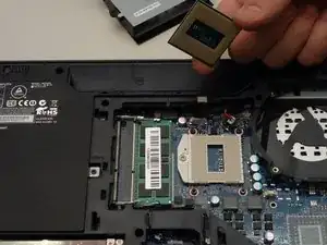
Unlock the processor using a small Torx screwdriver by turning the lock 180 degrees counterclockwise
-
Make sure the locking latch is pointing in the opposite direction.
-
You can now carefully remove the processor from its socket.
-
-
-
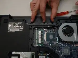
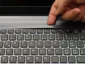
Press gently at the points indicated to release the LED cover strip.
-
Turn the laptop over, then lift the LED cover.
-
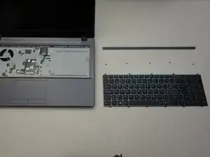
Remove the LED cover.
-
-
-
The five screws that anchor the keyboard are now visible.
-
Start by removing the first screw.
-
Remove the remaining screws (2-5).
-
-
-
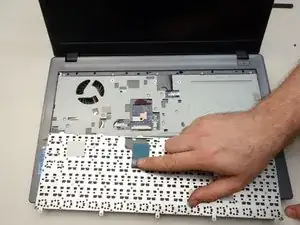
Dismount the keyboard from the chassis.
-
Flip the keyboard forward, taking care as it is still connected by a cable to the motherboard.
-
Release the cable latch on the right side of the motherboard connector with a small flat blade screwdriver.
-
-
-
Release the cable latch on the left side of the motherboard connector.
-
Slide the cable straight out from its connector.
-
Remove the keyboard.
-
-
-
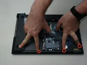
To access the motherboard first remove the three screws as shown in the first image of this step.
-
Remove the three screws as shown in the second image of this step.
-
Remove the two screws as shown in the third image of this step.
-
-
-
Remove the three screws as shown in the first image of this step.
-
Remove the screw as shown in the second image of this step.
-
Remove the last screw as shown in the third image of this step.
-
-
-
Of all the screws you just removed the two screws that are longer than the others correspond to the locations shown in the first image of this step.
-
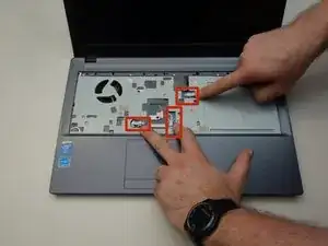
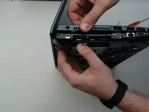
Flip the laptop over and locate the three connecting cables as shown in the second image of this step.
-
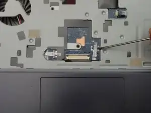
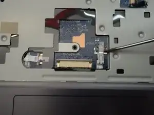
Use a small screwdriver to release the latch on the right of the flat cable.
-
-
-
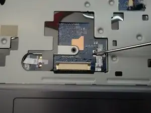
Release the lock on the left side of the ribbon cable.
-
Carefully remove the flat cable from its connector.
-
Repeat for the other two ribbon cables before you start removing the motherboard top cover.
-
-
-
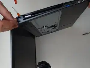
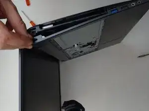
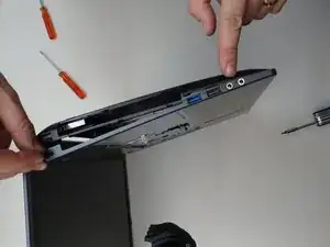
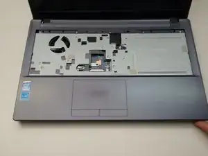
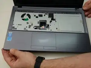
Follow the steps shown in the first two images in this step.
-
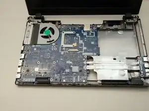
Once the top cover has been removed, you can now clearly see the motherboard.
-
-
-
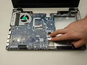
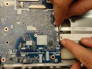
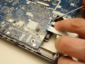
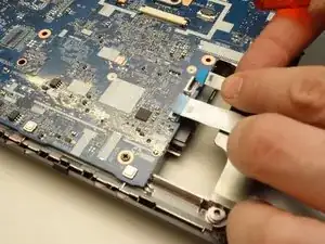
Locate the two ribbon cables as shown in the first image of this step. These two ribbon cables must be disconnected from the motherboard.
-
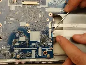
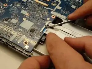
Release the latch on the first ribbon cable.
-
Once the latch is released,...
-
-
-
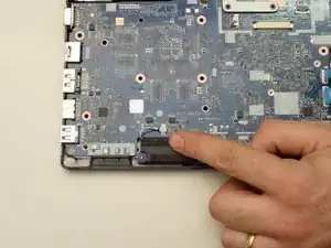
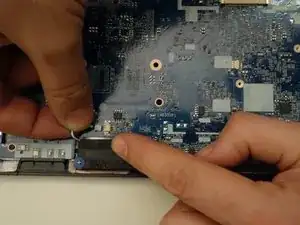
Locate the motherboard connector pointed to in the first image of this step.
-
Remove the connected cable.
-
Locate the two motherboard connectors shown in the third image of this step.
-
-
-
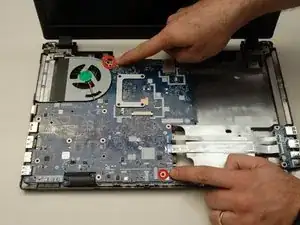
Locate and remove the two screws securing the motherboard.
-
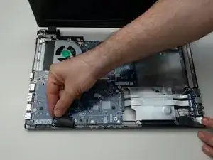
Before lifting the motherboard, remove the speakers.
-
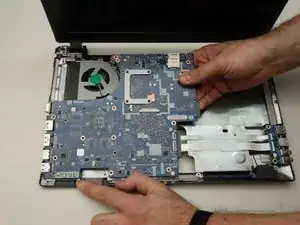
Carefully remove the motherboard.
-
To reassemble your device, follow these instructions in reverse order.
