Introduction

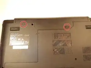
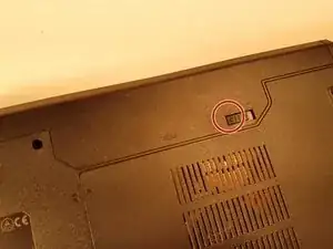
  1. 1QmsO55qVEqaxFj2
    1QmsO55qVEqaxFj2
    btcKGXIaheNWF6Kq
    UXHA5TCuYesDsyAr
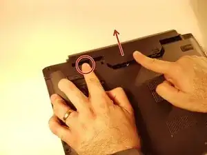
    • Unlock the button without spring

    • Slide the battery up while unlocking the button with spring

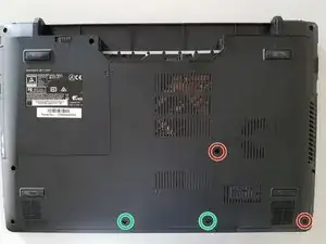
  2. M3AhURTVYXg4KtDg
    M3AhURTVYXg4KtDg
    gDHrZdbjUuQmvtbX
    4eMIcAX1MQMwLGQb
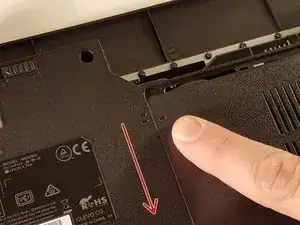
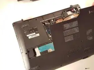
    • Unscrew the two large screws circled in red

    • Unscrew the two small screws circled in green

    • Slide the plate down and lift the

  3. BIsGMMOdhytInGGW
    BIsGMMOdhytInGGW
    peTTpWlCohRpuDOV
    XJtQruvkZTmZk4ju
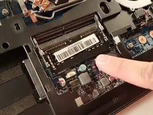
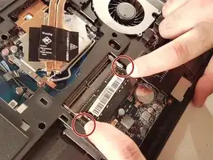
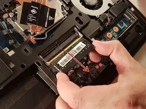
    • Spread the two arms holding the RAM bar

    • Remove the RAM card

  4. KJBnM5ncMSB25NiS
    KJBnM5ncMSB25NiS
    FlsAGgqXZAhq1kls
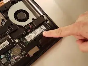
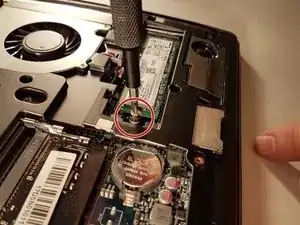
    • Unscrew the screw circled in red

    • Remove the SSD

  5. ZlPcRFFyHePZvGog
    ZlPcRFFyHePZvGog
    XGBFLbC53GAiTGcB
    O2PixoTOn5j5CENX
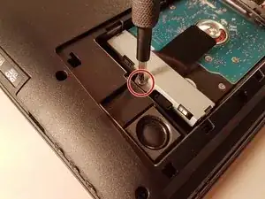
    • Unscrew the screw circled in red

    • Pull the black tab up

  6. tSkekkltnODBdHFa
    tSkekkltnODBdHFa
    AODDt2k2iJrVETc1
    Z5wpXn1lJWIUY5CD
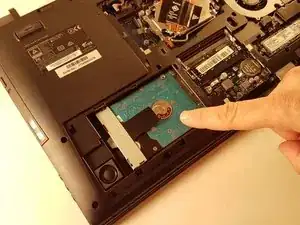
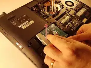
    • Unscrew the screw circled in red

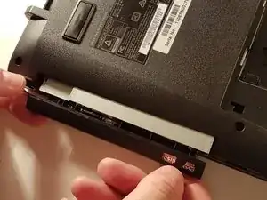
    • Push the drive to the location indicated by the green arrow

    • Remove the drive from its location

  7. Dpgv1PKYVG64Tf4K
    Dpgv1PKYVG64Tf4K
    i5SaL5YdmoWfLy6w
    Xid61FPBUoUReJNL
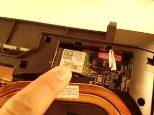
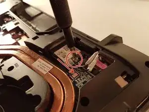
    • Unscrew the screw circled in red

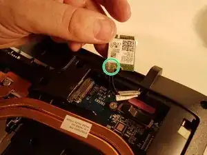
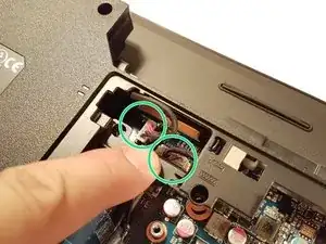
    • Disconnect the WLAN card in the direction of the red arrow

    • Unhook the two connectors circled in green on the WLAN card

  8. pIeuSn1mhPI6CCdq
    pIeuSn1mhPI6CCdq
    g5ZlurTUMEKIGISc
    A6NEDkYkRNfUqqSV
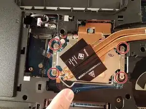
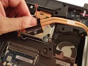
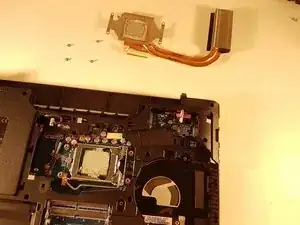
    • Unscrew the four screws circled in red

    • Lift the radiator with the black label

  9. UbhXP6PZ32gH6H6r
    UbhXP6PZ32gH6H6r
    uqoEUTaRRSBoIkmU
    qlJ3jUtYVJOGKbDj
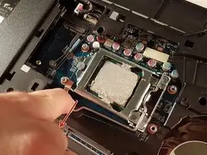
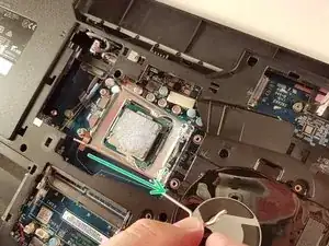
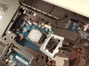
    • Push the lever in the direction of the red arrow while pushing it in

    • Lift the lever in the direction of the green arrow

    • Do not touch the bottom of the processor and take it by the sides

  10. ntoKNQnYbHHAZr6P
    ntoKNQnYbHHAZr6P
    LaENBLjerR6YWYMg
    kSoRoImGYAxSVksV
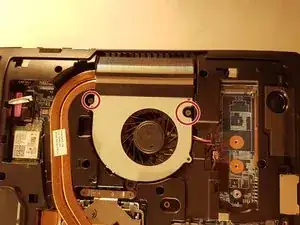
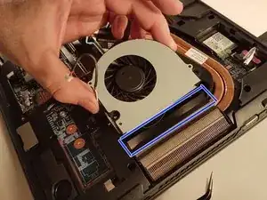
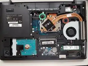
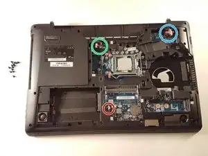
    • Unscrew the two screws circled in red

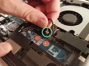
    • Disconnect the connector surrounded in green

    • Remove the fan by lifting the blue framed tab

  11. cFACQMPTALYpZIhW
    cFACQMPTALYpZIhW
    ctZf6OAIJAadfFvL
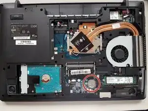
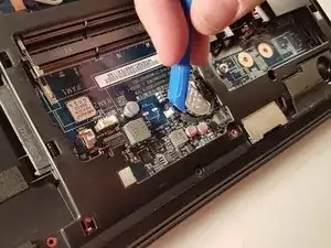
    • Remove the battery using a flat screwdriver

  12. 3QOYXMPeFGyPu1yI
    3QOYXMPeFGyPu1yI
    sX11imX3kkHTWgVf
    Gow6ulFLONAJrtWo
    • Unscrew the circled screws in red and green

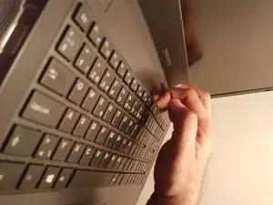
    • Put the computer in the position of the second image while pushing a paper clip into the hole of the screw circled in green until you hear a click

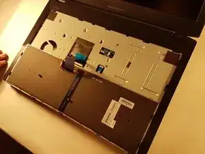
    • Lift the keyboard

  13. YdgAJJX2pNVW1txG
    YdgAJJX2pNVW1txG
    Cu2Z4lfXxWFi3PWC
    pNOEhj2xMPua5K6t
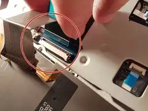
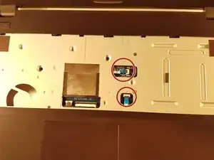
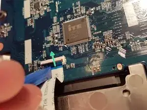
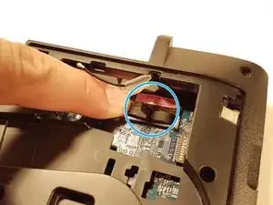
    • Remove the red circled connector

    • Pull the white drawer that holds the connector circled in blue in the direction of the green arrow

    • Remove the connector surrounded in blue

  14. WUDdN6YTwfUSQQuV
    WUDdN6YTwfUSQQuV
    vUAOsrhAZSEDELQG
    xNmONPriCvTuPgJB
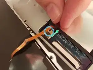
    • Lift the two black flaps

    • Remove the two connectors circled in red

  15. QyPp4du42hrlN2Bv
    QyPp4du42hrlN2Bv
    abpShVYfDkRwJQuf
    uGwtVS3yZksyDSC1
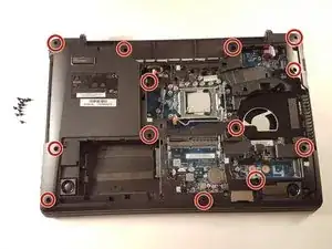
    • Remove the thirteen screws circled in red

    • Remove the top cover

  16. XW5RcRZhTrUTFms2
    XW5RcRZhTrUTFms2
    YHeV5JHUYdjTgZTH
    mJudHlHIQJSbZsn2
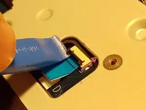
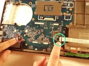
    • Lift the blue flap that holds the connector circled in green

    • Disconnect the connector surrounded in green

    • Disconnect the red circled connector

  17. XJi3tP6uROrLS2Or
    XJi3tP6uROrLS2Or
    3uFtI6Xh2CAT1ePr
    TqLPrZyhvJCHYks2
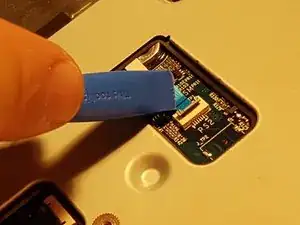
    • Disconnect the two connectors located in the green zone

    • Disconnect the connector surrounded in blue

    • Disconnect the red circled connector

  18. IXGhCPNSdeco4k6N
    IXGhCPNSdeco4k6N
    LncZtB4BPqIX1tPm
    jqB1iaJKGeXkCZE5
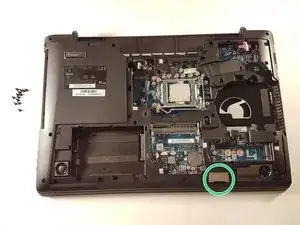
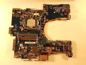
    • Remove the Micro SD port cover that is circled in green if there is one

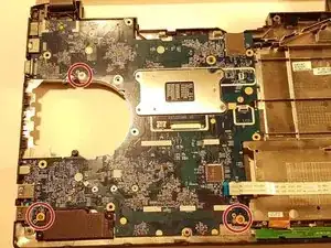
    • Unscrew the three screws circled in red

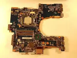
    • Carefully remove the motherboard

Conclusion

To reassemble your device, follow the instructions in reverse order.
Felice Suglia

Member since: 15/06/13

30527 Reputation

0 comments