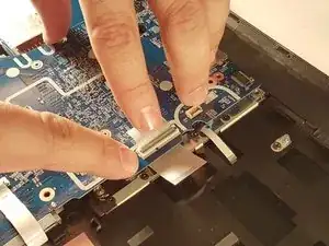
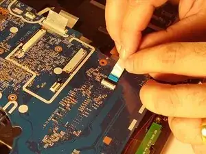
Introduction

  1. oWZXYSZydykU13AA
    oWZXYSZydykU13AA
    owClZZr5jXYwXYOB
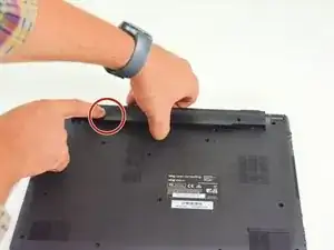
    • Start by unlocking the right locking latch.

    • Then, by simultaneously unlocking the left latch, lift the battery out of its socket.

  2. 2e3elDx1XyBDJjTy
    2e3elDx1XyBDJjTy
    cvwdW1OuPhXtrYV2
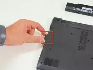
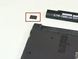
    • Begin by spotting the dummy memory card.

    • Then, remove it and put it on your workplan.

  3. St1ClPjGw3naYO5o
    St1ClPjGw3naYO5o
    wbLs5MRPrleLjDrC
    2XTP32uvfOm1CxbC
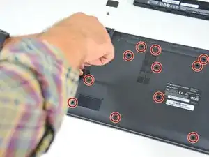
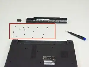
    • Locate the 15 screws that hold the bottom cover of the device in place.

    • Unscrew them and place them on your work surface.

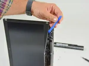
    • Then, un-clip the bottom cover, starting with the side shown in the third picture.

  4. Hv2mLCfRLRK2ZyKr
    Hv2mLCfRLRK2ZyKr
    XkDEDHbt4ZfVWwUn
    FEXGwUlb2CCoJdld
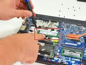
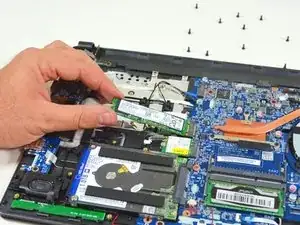
    • Locate the M.2 SSD in its slot.

    • Unscrew the fastening screw of the latter.

    • Lift and remove the SSD M.2 drive from its connector.

  5. kNJAbGEXNRhZZBdH
    kNJAbGEXNRhZZBdH
    dVuDirW11tMXjEXa
    VmF6FCcDI2F1hWh5
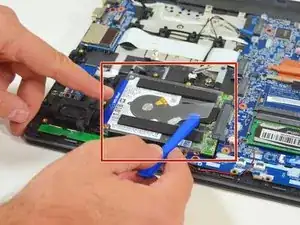
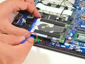
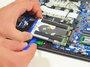
    • Locate the hard drive in its location.

    • Lift it slightly.

    • Finally remove it from its SATA connector.

  6. lKsecfHslN55m2YO
    lKsecfHslN55m2YO
    HmcBlxWFNrqTPxYZ
    • To reassemble your device, follow the instructions in reverse order.
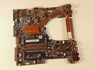
    • Lift it gently and take it out of its place.

  7. MfuYdSUlsX1npoWY
    MfuYdSUlsX1npoWY
    gPdepIJMamyuB3xI
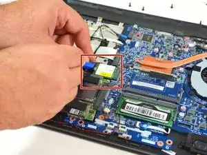
    • Carefully unplug the MAIN and AUX antennas.

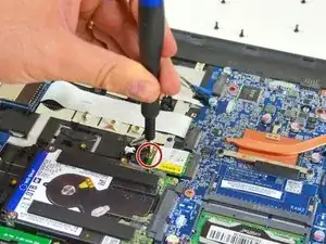
    • Unscrew the fixing screw with the Philips # 0 screwdriver. Then lift the chipset slightly and remove it from the connector.

  8. xIjaVkyKsY3LJUjF
    xIjaVkyKsY3LJUjF
    odrZbZFvekwWnQId
    rE5EeuSdTPxVpDem
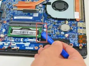
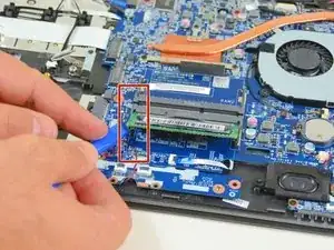
    • Find and separate the spring blades that maintain the memory module in place (right).

    • Find and separate the spring blades that maintain the memory module in place (left).

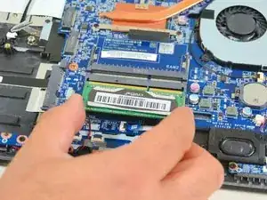
    • Remove the memory module (RAM) from its connector.

  9. Jp4BdBJBabBkSoAQ
    Jp4BdBJBabBkSoAQ
    SODQukmdMGVMBofZ
    ZXq3eYd1l2cy4Hu5
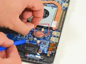
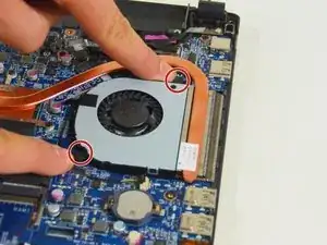
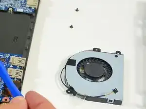
    • Remove the power cable from the fan.

    • Unscrew the two screws securing the fan.

    • Finally remove the fan and place it on your worktop.

  10. tLcemoZlaePG13gi
    tLcemoZlaePG13gi
    GCCOsArHFjWxZlPE
    6uZ6cOhNWBGU6trg
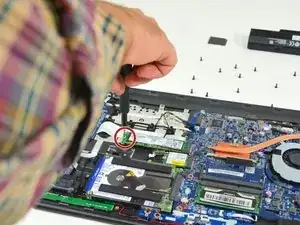
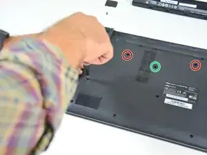
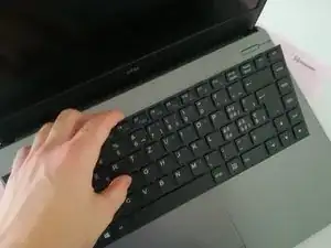
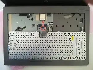
    • Unscrew the circled screws in green and red

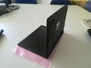
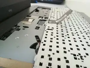
    • Put the computer in the position of the second image while pushing a paper clip into the hole of the screw circled in green until you hear a click

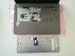
    • Lift the keyboard

  11. qyiAmHEFYnaRrjiU
    qyiAmHEFYnaRrjiU
    ILs4Whkvwvv5KrOu
    5Mp6J3wc5COKWrBL
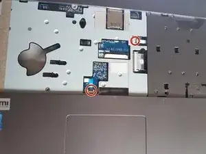
    • Disconnect the connector circled in red in the direction of the arrow

  12. qexIbD6VckIENXj6
    qexIbD6VckIENXj6
    DJYhydRZi4mvnOdH
    X56NTCjURVxfUkyC
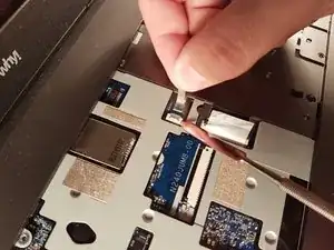
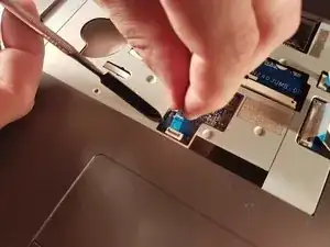
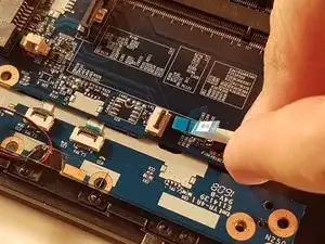
    • Locate the two flat cables and remove them carefully.

  13. BtjDxvfSbZEWFywf
    BtjDxvfSbZEWFywf
    ZfIRRwCxCXHZH3GH
    sUkXhOwvHa4lMp4p
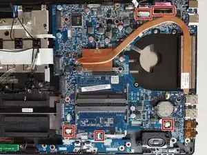
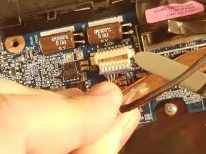
    • Locate the five connectors on the motherboard

    • Unplug all connectors

  14. yGDhIcydaVBLlm11
    yGDhIcydaVBLlm11
    5uEIa5PCPU2PMgY6
    PCayaSb5XApspFwL
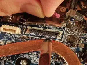
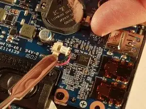
    • Unplug all connectors

  15. cof1faNLgWKsIw42
    cof1faNLgWKsIw42
    OnDuByd4EO4GkLvt
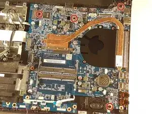
    • Unscrew the four screws circled in red

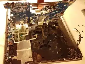
    • Lift the motherboard by taking it through the radiator

  16. uHDxrSrfbJZMwPIN
    uHDxrSrfbJZMwPIN
    ZdTV5sxMcrih2vST
    USYRXIJNceLmddGR
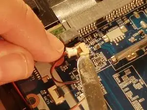
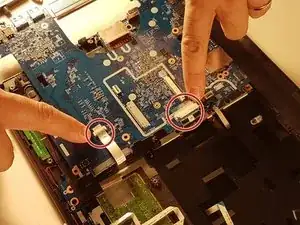
    • Disconnect the two connectors circled in red

Conclusion

To reassemble your device, follow the instructions in reverse order.
Felice Suglia

Member since: 15/06/13

30527 Reputation

0 comments