Introduction
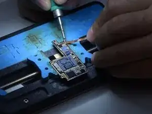
To separate and recombine the double-stacked motherboard is a very important step for motherboard repair of iPhone X and models above. Slight errors may result in pseudo soldering or other problems. REWA Academy students recently gave feedback that the two layers often fail to fit closely in double-stacked motherboard repair. There are even large gaps, causing pseudo soldering. In response, we will share tips and notes when separating and recombining double-stacked motherboard. The tips in this article apply to iPhone X and models above.
-
-
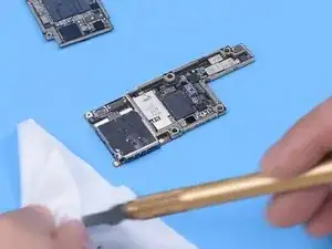
Peel off foam on the motherboard before heating.
-
Please be noted that we do not recommend beginners to heat the motherboard with a hot air gun. Because the motherboard may receive heat unevenly and deform. A professional motherboard heating platform is what we suggest.
-
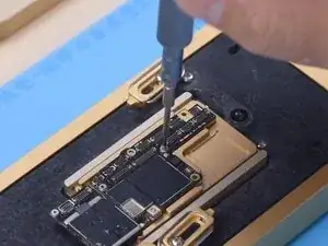
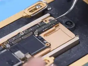
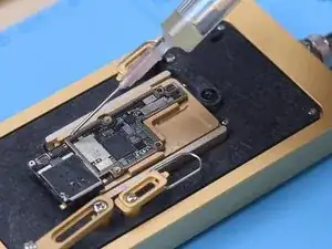
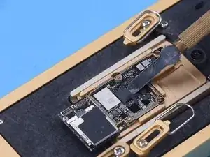
To facilitate later removal of the logic board, drive a screw on the logic board.
-
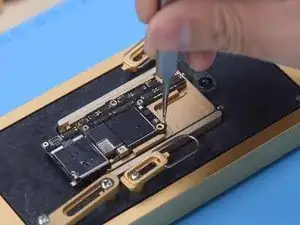
Cut through the tape with a Sculpture Knife.
-
-
-
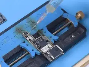
The logic board and middle layer are soldered with low-temperature solder paste. So the best temperature for the heating platform will be 155 °C-165 °C.
-
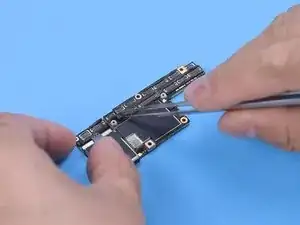
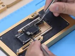
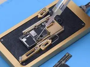
Push the logic board gently with tweezers when the temperature reaches 165 °C. If the logic board is loose, the tin has melted.
-
-
-
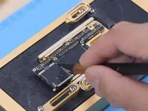
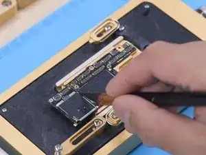
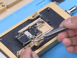
Remove thermal grease with a Sculpture Knife.
-
Thermal grease must be removed completely. Otherwise, the thermal grease will touch the logic board to give rise to pseudo soldering in recombination.
-
Attach the signal board to the holder and apply a round of Paste Flux.
-
-
-
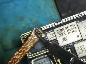
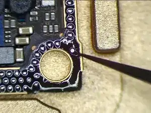
Remove tin on the bonding pad with Soldering Iron at 365 °C and Solder Wick.
-
Tin on the bonding pad must be completely removed. The residual tin will affect the subsequent soldering.
-
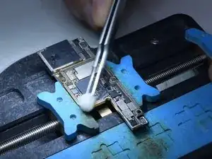
Clean the bonding pad with PCB Cleaner.
-
Clean the logic board with the same method. Please do not damage components around the bonding pad of the logic board while cleaning. It is necessary to check if the bonding pad is neat after cleaning.
-
-
-
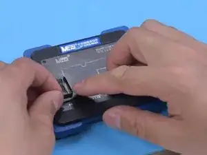
Attach the signal board to the Reballing Platform. Put the reballing stencil in position to make sure that it is pressing against the signal board.
-
To prevent the solder paste from flowing into the motherboard gap, insert a metal plate.
-
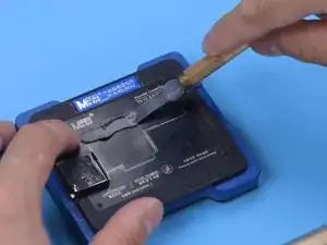
Apply a layer of low-temperature Solder Paste and wipe off excess solder paste with a Lint-free Wipe. Remove the reballing stencil. Check if solder paste on the signal board is full.
-
-
-
While applying solder paste, please make sure that solder paste must have a certain humidity.
-
If the solder paste is too dry, it will adhere to the reballing stencil when the stencil is removed. As a result, the solder paste on the signal board will not be uniform, which can easily lead to poor soldering.
-
-
-
Put the signal board on the 165 °C Heating Platform to heat. Stop heating after the solder balls are formed.
-
Apply a small amount of Paste Flux after the signal board has cooled.
-
-
-
Align the logic board with the signal board. Keep heating on the 165 °C Heating Platform. When the solder flux spills and logic board sinks, nudge the logic board gently with tweezers to ensure the two layers fit closely. The nudge must be gentle and small.
-
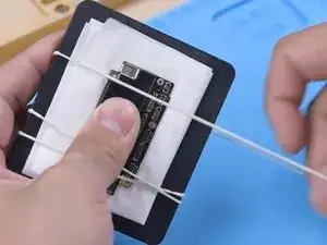
Clean the motherboard with PCB Cleaner after the motherboard has cooled. If you find the motherboard deformed while recombining, you can put the motherboard on a flat board and fasten it with a rubber band. Press two sides of the motherboard gently. To avoid crushing components, please put a soft paper under the motherboard.
-
-
-
Next, we will share another recombination method. The method can be taken if the middle bonding pad is not damaged.
-
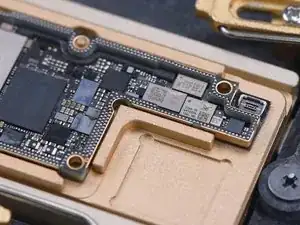
When the tin melts, remove the logic board in a vertical manner with tweezers. It can be seen that there is a metal pad of 0.05 mm thickness around the signal board at a certain distance. This metal pad is designed to keep a 0.05 mm gap between the logic board and the middle layer, preventing the solder balls from bridging while soldering.
-
You only need to remove thermal grease on the motherboard when the repair is done. Keep original tin on the bonding pad and apply a small amount of Paste Flux.
-
Lastly, align the logic board with the signal board. When the temperature reaches 165 °C and the tin melts, turn the power off. Press two ends of the logic board with tweezers until the motherboard has cooled. The logic board and the signal board fit closely in this way. There will be no bridging and solder balls spillover.
-


To reassemble your device, follow these instructions in reverse order.

One comment
What about thermal grease? it was originally there for a purpose. I don't see much information about this on the Internet. It might be a good idea to use a soft/liquid thermal paste that is non-conductive? I don't get it why it's suggested to remove that original grease with second method if you can press the boards and that will also press the grease to fit.