Introduction
-
-
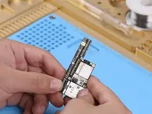
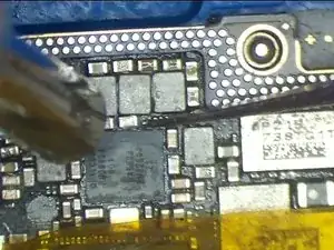
First, run a cosmetic inspection of the motherboard. The motherboard is not deformed or water damaged.
-
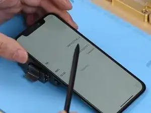
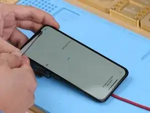
Next, let's install the motherboard and connect the battery and display assembly. Turn on the phone and the phone goes with the activation process. Click the icon at the bottom right corner. Serial number displays normally on the screen. No IMEI number on the screen. The phone shows a No Service error in the upper-right corner.
-
-
-
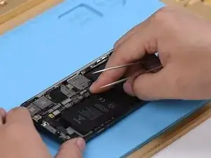
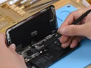
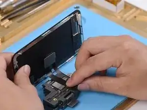
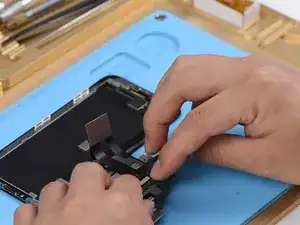
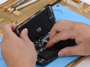
In the first place, remove the display assembly, disconnect the battery, and take out the motherboard.
-
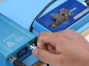
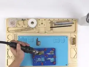
Place the motherboard on the specialized Heating Platform. Power on the heating platform and set the temperature to 150℃.
-
-
-
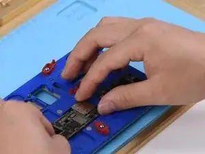
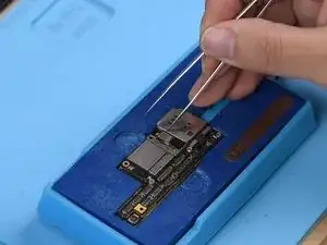
With the temperature of the platform reaching 150℃, pick up the upper layer with tweezers.
-
Continue to take the lower layer off the platform and power off the heating platform.
-
-
-
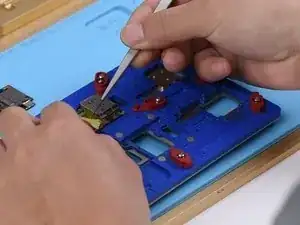
Attach the upper layer and the lower layer to the PCB Holder.
-
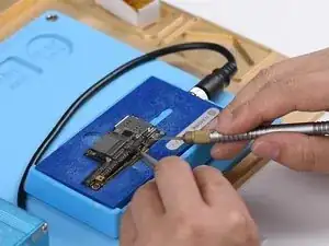
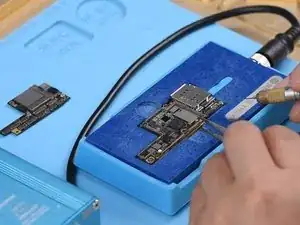
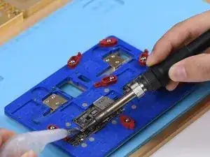
Heat up with the Soldering Iron at 360℃ and clean pads on edges of the upper layer and the bonding pad with rosin soaked Solder Wick.
-
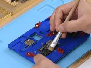
Clean with PCB Cleaner afterwards.
-
-
-
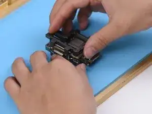
Detach the upper layer and the lower layer from the PCB Holder. Attach the upper layer and the lower layer to the test fixture.
-
Get the display assembly connected. Connect the battery connector with the Power Supplier. And press power button on the Power Supplier. The system will then detect power button press.
-
-
-
The phone goes with activation process. Click the icon at the bottom right corner. Serial number displays normally on the screen. No IMEI number on the screen. The phone shows a No Service error in the upper-right corner.
-
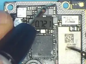
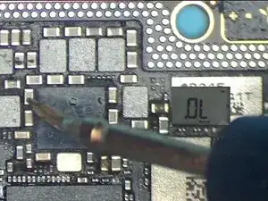
Run diode mode measurement of signal relevant pins on the bonding pad. Nothing goes wrong.
-
Continue to run diode mode measurement of capacitors related to the power supply circuit of U_PMIC_E. Nothing goes wrong.
-
-
-
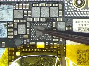
Let's try to replace with a new U_PMIC_E and see how it works. First, stick High-temperature Tape on U_MDM_E and the WiFi module.
-
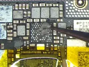
Remove U_PMIC_E with Hot Air Gun at 330℃, air flow 3.
-
-
-
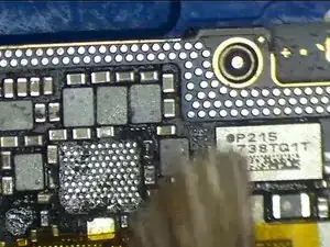
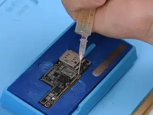
Continue to apply Solder Paste and Paste Flux to the bonding pad.
-
Clean the bonding pad with Soldering Iron at 360℃.
-
Continue to heat with Hot Air Gun at 330℃ and clean the bonding pad with Solder Wick.
-
-
-
Clean with PCB Cleaner afterwards.
-
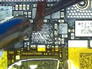
There is black adhesive around the bonding pad of U_PMIC_E. So we need to remove the black adhesive with tweezers before soldering.
-
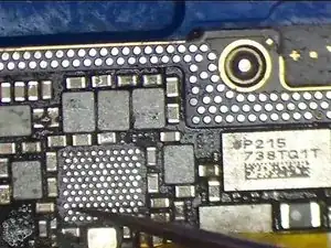
Once done, apply Paste Flux to the bonding pad. Get a new U_PMIC_E in position and solder with Hot Air Gun at 330℃, air flow 3.
-
After that, clean with PCB Cleaner and tear off the High-temperature Tape.
-
-
-
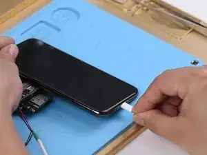
Attach the upper layer and the lower layer to the test fixture. Get the back glass assembly connected. Connect the battery connector with the DC Power Supply.
-
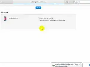
Connect the iPhone to the computer with the USB cable. Restore the phone via iTunes. Once done, disconnect the USB cable, the power supply, and the back glass assembly.
-
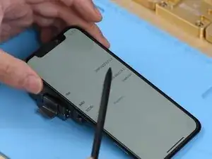
Again, let’s get the display assembly installed. Connect the battery connector with the Power Supplier. The phone goes with activation process.
-
Click the icon at the bottom right corner. Serial number and IMEI number display normally on the screen. Signal bars in the upper-right corner is back to normal. We can confirm now that the No Service problem is caused by U_PMIC_E.
-
-
-
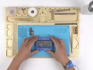
Next thing we need to do is to solder the two layers together. Attach the lower layer to iPhone X specialized reballing mold.
-
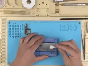
Cover the lower layer with the matched reballing stencil.
-
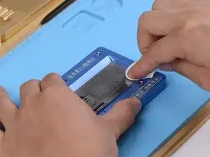
Smear some low-temp Solder Paste on the stencil. Wipe off excess solder paste with the lint-free wipe. Once done, remove the matched reballing stencil carefully. Make sure solder paste has been applied evenly and perfectly.
-
-
-
Continue to place the lower layer to the heating platform. Power on the heating platform and set the temperature to 150℃. With solder paste melting, solder balls start to shape up. Once completed, power off the heating platform and wait for the lower layer to cool for 10 minutes.
-
Continue to apply BGA Paste Flux to the bonding pad.
-
Get the upper layer in position and power on the heating platform.
-
With the temperature of the platform reaching 150℃, continue heating for 1 minute. Once done, power off the heating platform. Wait for the motherboard to cool for 10 minutes.
-
-
-
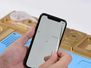
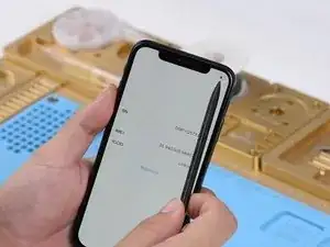
Now we can assemble the phone and test. The phone turns on normally and goes with activation process. Click the icon at the bottom right corner. Serial number and IMEI number display normally on the screen. Signal bars in the upper-right corner is back to normal. The No Service fault has been cleared.
-
To reassemble your device, follow these instructions in reverse order.

One comment
working ♥️♥️