Introduction
Internal prerequisite.
-
-
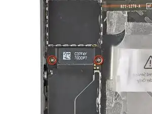
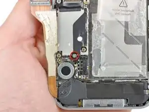
Remove the two 1.8 mm Phillips screws securing the dock connector cable to the logic board.
-
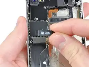
Remove the thin metal dock connector cable cover.
-
-
-
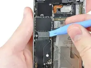
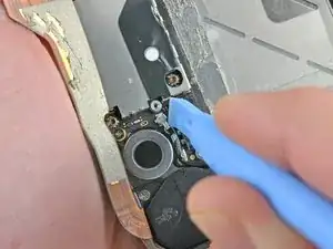
Use the edge of a plastic opening tool to pry the dock cable up from its socket on the logic board.
-
-
-
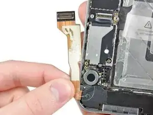
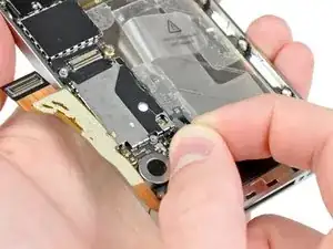
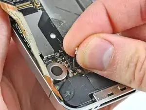
Peel the dock connector cable off the adhesive securing it to the logic board and the side of the speaker enclosure.
-
-
-
Remove the 1.6 mm Phillips screw securing the pressure contact to the logic board near the vibrator.
-
Remove the pressure contact.
-
-
-
Use the edge of a plastic opening tool to pry the cellular antenna cable up from its socket on the logic board.
-
De-route the cellular antenna cable out from under the metal fingers attached to the logic board.
-
To reassemble your device, follow these instructions in reverse order.
