Introduction
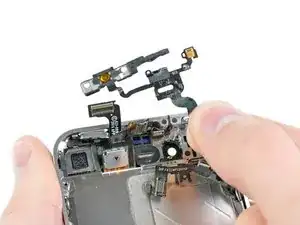
This part contains the proximity sensor, ambient light sensor, power cable and second microphone used for noise canceling.
Tools
Parts
-
-
Power off your iPhone before beginning disassembly.
-
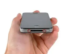
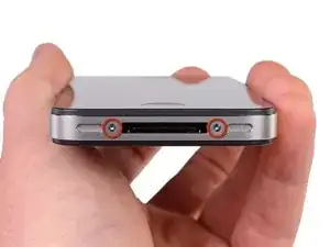
Your iPhone 4 rear cover may have either two #000 Phillips screws or Apple's 5-Point "Pentalobe" screws (second image). Check which screws you have, and ensure you also have the correct screwdriver in order to remove them.
-
Remove the two 3.6 mm Pentalobe or Phillips #000 screws next to the dock connector.
-
-
-
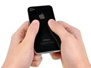
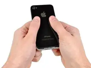
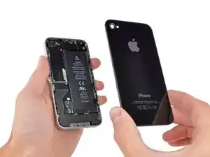
Pinch the rear panel with your fingers and lift it away from the iPhone. Alternatively, use a Small Suction Cup .
-
-
-
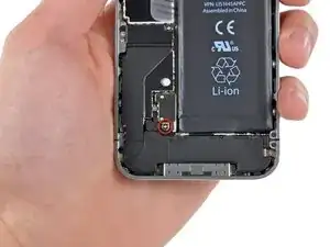
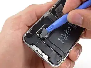
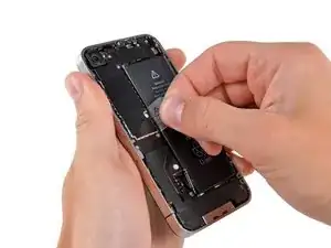
Use a plastic opening tool to gently pry the battery connector up from its socket on the logic board.
-
Remove the metal clip covering the antenna connector.
-
-
-
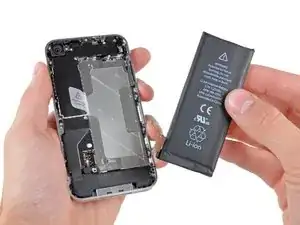
Use the clear plastic pull tab to gently lift the battery out of the iPhone.
-
If there's any alcohol solution remaining in the phone, carefully wipe it off or allow it to air dry before installing your new battery.
-
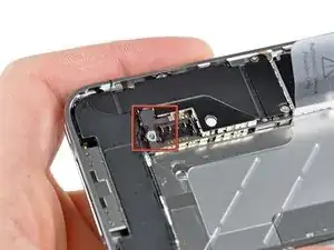
Before reconnecting the battery connector, be sure the contact clip (shown in red) is properly positioned next to the battery connector.
-
-
-
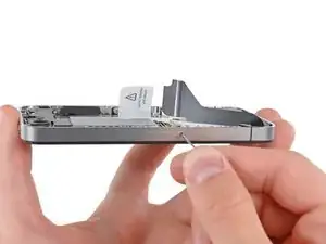
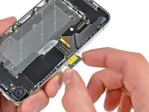
Use a SIM card eject tool or a paperclip to eject the SIM card and its holder.
-
Remove the SIM card and its holder.
-
-
-
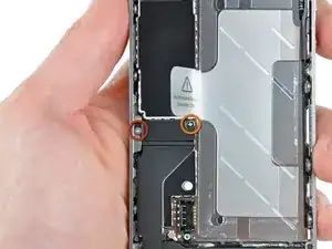
Remove the following two screws:
-
One 1.2 mm Phillips
-
One 1.6 mm Phillips
-
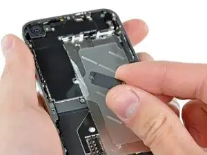
Remove the thin steel dock connector cable cover from the iPhone.
-
-
-
Use an iPod opening tool to gently pry the dock cable connector up off the logic board from both short ends of the connector.
-
-
-
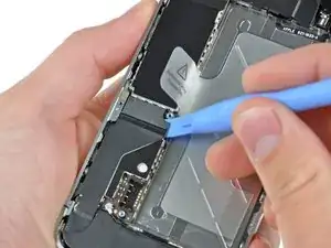
Use a plastic opening tool to pry the lower antenna connector up off its socket on the logic board.
-
-
-
Remove the following five screws securing the Wi-Fi antenna to the logic board:
-
One 2.3 mm Phillips
-
Two 1.6 mm Phillips
-
One 1.4 mm Phillips
-
One 4.8 mm Phillips
-
-
-
Use an iPod opening tool to slightly lift the top edge of the Wi-Fi antenna away from the logic board.
-
Use the tip of a spudger to pull the Wi-Fi retaining clips away from the inner frame.
-
Remove the Wi-Fi antenna from the iPhone. Make sure you don't lose the metal clips on the top of the cover where the 4.8mm screw attaches or the 4.8mm screw. That's the primary reason for abnormal Wi-Fi performance after the reassembly.
-
-
-
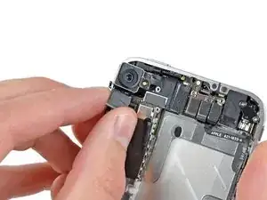
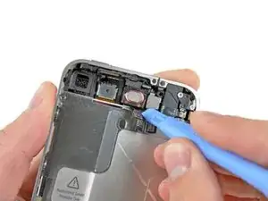
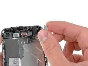
Use an iPod opening tool to carefully lift the rear camera connector up off its socket on the logic board.
-
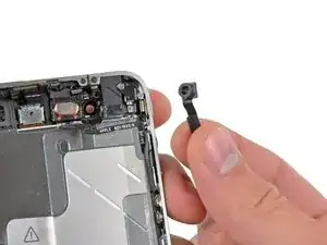
Remove the rear camera.
-
-
-
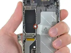
Remove the small circular white sticker (warranty sticker and water indicator) covering the screw near the battery pull tab.
-
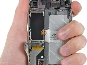
Remove the 2.4 mm Phillips screw that was hidden underneath the sticker.
-
-
-
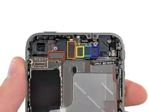
Use the edge of a plastic opening tool to gently pry the following connectors up and out of their sockets on the logic board:
-
Digitizer cable (pry from bottom)
-
LCD cable (pry from bottom)
-
Headphone jack/volume button cable (pry from top)
-
Top Microphone/sleep button cable (pry from top)
-
Front camera cable (pry from top)
-
-
-
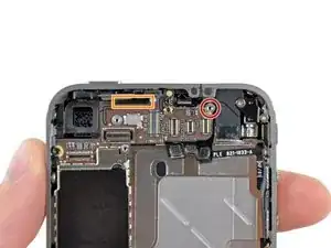
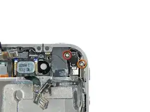
Remove the 4.8 mm standoff screw near the headphone jack.
-
Without this part, the motherboard could damage the ribbon cables around it.
-
-
-
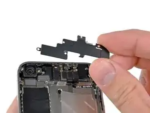
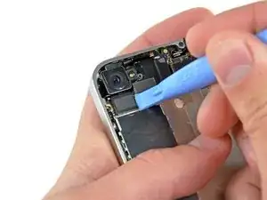
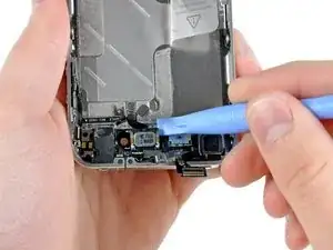
Use the edge of a plastic opening tool to lift the thin steel front camera retainer off the front camera.
-
Remove the front camera retainer.
-
-
-
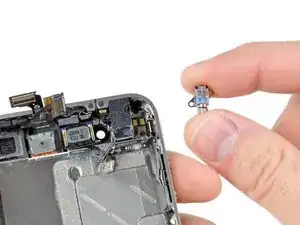
Remove the following two screws securing the vibrator to the inner frame:
-
One 6 mm Phillips
-
One 1.4 mm Phillips
-
Remove the vibrator from the inner case.
-
-
-
Use the edge of a plastic opening tool to pry the earpiece speaker away from the adhesive securing it to the front panel.
-
-
-
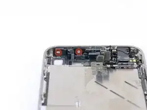
Remove the two Phillips #000 screws securing the power button bracket to the outer case.
-
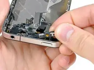
Carefully pull the power button bracket up and out of the outer case.
-
-
-
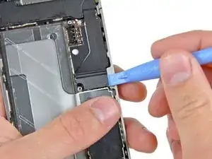
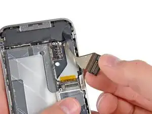
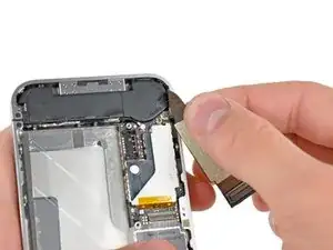
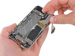
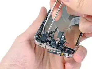
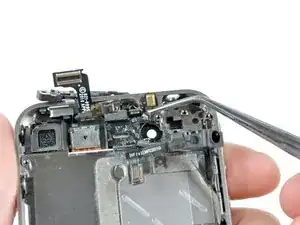
Grab the power & sensor cable near the microphone and peel it off the front panel, being careful not to rip it in the process.
-
-
-
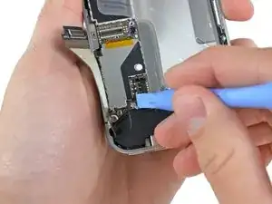
Also be sure to transfer the proximity sensor foam/UV-filter adhered to the old power & sensor cable if your new one does not already come with one. It looks like a small square and can be peeled off with tweezers.
-
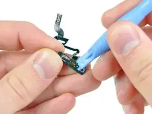
Transfer the bracket to your new power & sensor cable.
-
To reassemble your device, follow these instructions in reverse order.
24 comments
Be careful removing the headphone adapter, the ribbon is very easy to rib with the metal brace beneath it.
Thank you very much for the, it has been very useful for my to change the power and sensor cable.
You are doing a very good job in this web.
Now this is more helpful, than the power button repair guide that they gave us. This one still kind of leaves me hanging on how I'm supposed to put the silver button back into the hole so that it makes contact with the orange dome(aka the powerbutton).
Anthony -
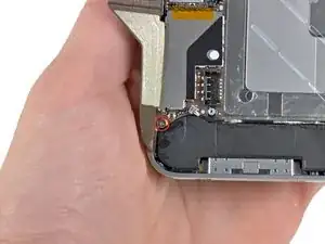
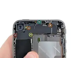
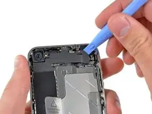
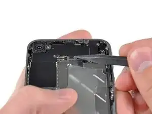

using something like the 18-compartment tray will GREATLY help with this one; there are over a dozen groups of parts. For re-assembly having a digital calipers to measure the 2.4 vs the 2.6mm screws also helps greatly.
awr -
My method for hardware management during delicate phone surgery is to take and print out on 8.5"x11' paper, one or more pictures of the open phone in various stages of disassembly, and then tape the screws to the appropriate spots on the pictures. Also write numbers on the pictures next the screws to indicate the order in which you removed them.
lens42 -
I use a plastic egg tray, I drop all the screws and small parts (like the camera) for each step into the same egg indentation. You can see that the screws are different lengths, so I don't put one screw into it's own spot. I used 5 egg indentations to replace my screen.
Mangled Jargon -