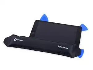
Introduction
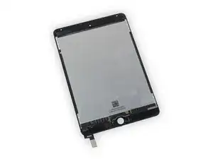
Follow the steps in this guide to replace your iPad mini 4 display assembly, including the fused LCD and digitizer glass.
This procedure involves removing the screen then transferring the home button to your new assembly. In order to maintain Touch ID functionality you must transfer your original home button to the new screen.
Depending on your replacement part, you may also need to transfer the sleep/wake sensor for Smart Cover use, this portion of the procedure requires desoldering a cable.
-
-
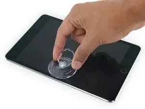
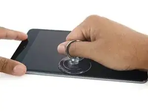
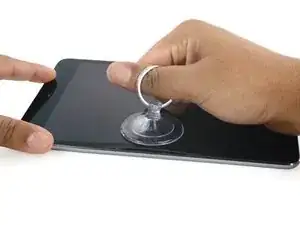
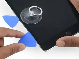
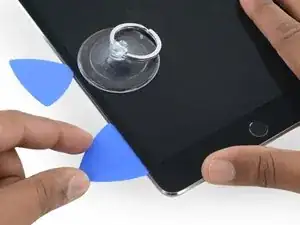
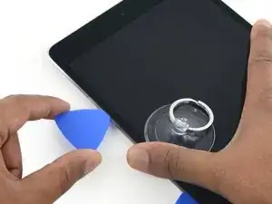
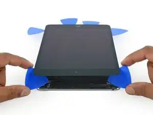
Apply a suction cup halfway up the heated side.
-
Be sure the cup is completely flat on the screen to get a tight seal.
-
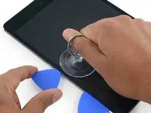
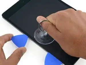
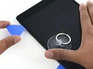
While holding the iPad down with one hand, pull up on the suction cup with strong, steady force to create a gap.
-
-
-
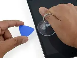
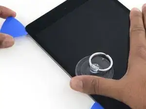
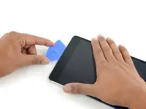
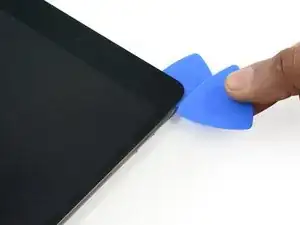
While holding the glass up with the suction cup, insert the point of an opening pick into the gap between the glass and body of the iPad.
-
-
-
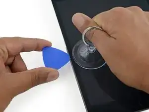
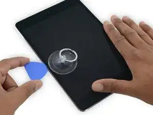
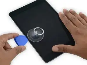
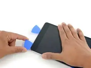
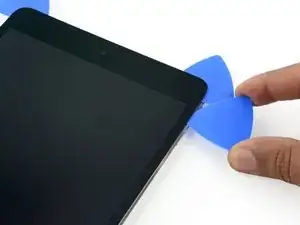
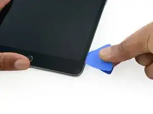
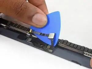
Insert a second opening pick alongside the first and slide the pick down along the edge of the iPad, releasing the adhesive as you go.
-
-
-
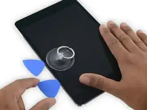
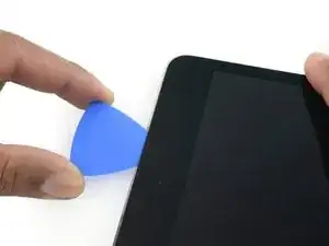
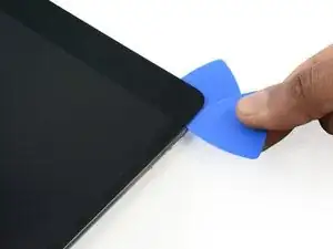
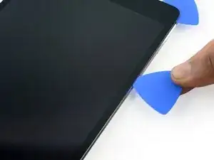
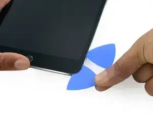
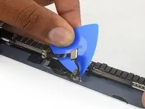
Continue moving the opening pick down the side of the display to release the adhesive.
-
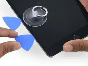
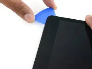
If the opening pick gets stuck in the adhesive, "roll" the pick along the side of the iPad, continuing to release the adhesive.
-
-
-
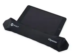
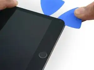
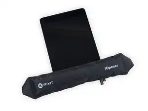
Reheat the iOpener and place it on the top edge of the iPad, over the front-facing camera.
-
If you have a flexible iOpener, you can bend it to heat both the upper left corner and the upper edge at the same time.
-
-
-
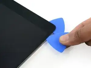
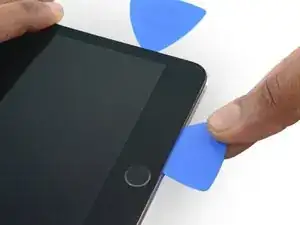
Slide the opening pick along the top edge of the iPad, stopping just before you reach the camera.
-
As you reach the front-facing camera, pull the pick out slightly and continue sliding it across the top edge.
-
-
-
Leave the opening pick in the iPad slightly past the front-facing camera.
-
Take a second pick and insert it to the left of the camera, where the first pick just was. Slide it back to the corner to completely cut any remaining adhesive.
-
Leave the second pick in place to prevent the corner adhesive from re-sealing as it cools.
-
-
-
Insert the previous pick deeper into the iPad and slide it away from the camera toward the corner.
-
-
-
Leave the three picks in the corners of the iPad to prevent re-adhering of the front panel adhesive.
-
Reheat the iOpener and place it on the remaining long side of the iPad—along the volume and lock buttons.
-
-
-
Insert a new opening pick and slide it down the right edge of the iPad, releasing the adhesive as you go.
-
-
-
Continue sliding the opening pick down the right edge of the iPad, reheating the edge using an iOpener if necessary.
-
-
-
Leave the opening picks in place and reheat the iOpener.
-
Set the reheated iOpener on the home button end of the iPad and let it rest for a few minutes to soften the adhesive beneath the glass.
-
-
-
Insert a new opening pick at the bottom right corner of the display, below the last opening pick you used to slice down the right edge.
-
Rotate the new pick around the lower right corner of the device.
-
-
-
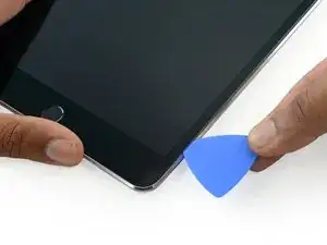
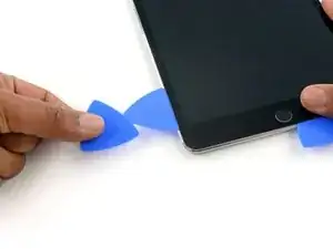
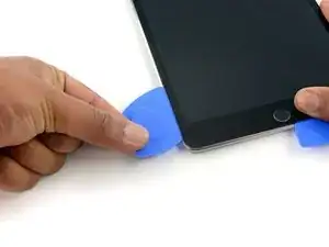
Slide the pick from the bottom right corner along the lower edge of the device. Stop about half an inch shy of the home button.
-
-
-
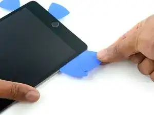
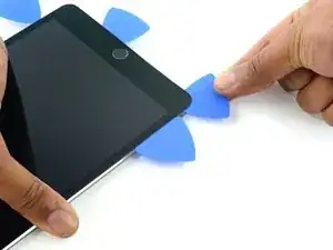
Insert a final opening pick at the lower left corner of the iPad, directly below the existing one.
-
-
-
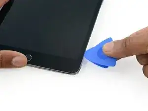
Continue sliding the pick at the lower left edge of the display toward the center of the iPad, until it is roughly half an inch from the home button.
-
-
-
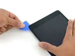
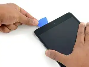
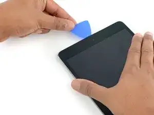
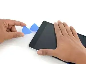
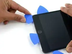
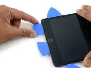
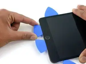
Twist the two picks at the top edge of the iPad to break up the last of the adhesive holding the display assembly in place.
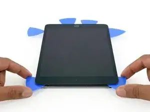
-
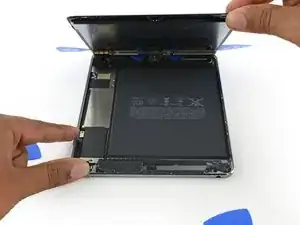
Lift the display from the top edge to open the device.
-
-
-
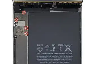
Use the flat tip of a spudger to disconnect the battery connector from its socket on the logic board.
-
-
-
Use the pointed end of a spudger to disconnect the display data connector from its socket on the logic board.
-
Use the pointed end of a spudger to disconnect the digitizer cable connector from its socket on the logic board.
-
-
-
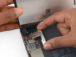
Use the pointed tip of a spudger to flip up the retaining flap on the home button ZIF socket.
-
-
-
Use tweezers to unplug the home button ribbon cable from the ZIF socket.
-
Continue peeling the ribbon cable up to the EMI shield.
-
-
-
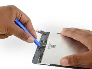
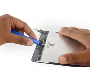
Use an opening pick to continue separating the home button ribbon cable from the display assembly.
-
-
-
Heat an iOpener and lay it over the lower edge of the front panel to soften the adhesive holding the home button in place.
-
-
-
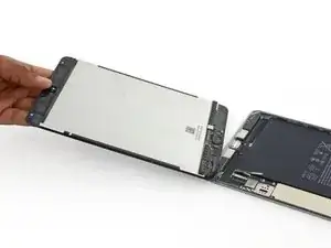
Slowly push the home button up and out of the display assembly to separate the gasket from the front panel.
-
-
-
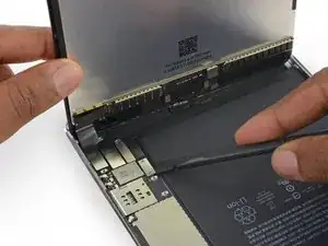
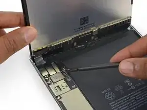
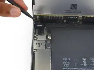
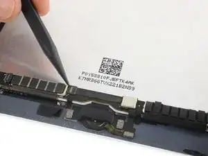
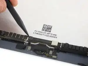
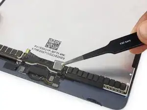
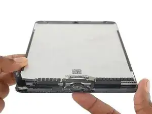
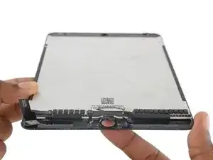
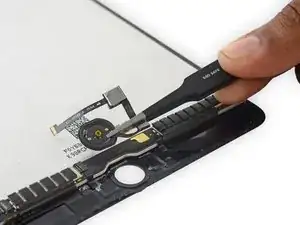
Examine your replacement part, and your original display carefully to be sure they match.
-
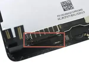
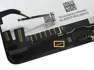
Your replacement screen may be missing the sleep/wake sensor that is necessary for Smart Cover use. If you want to maintain functionality you will need to transfer the component.
-
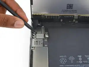
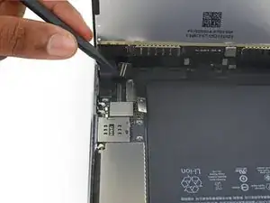
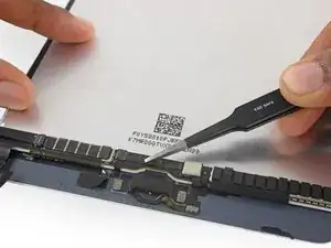
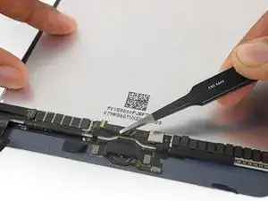
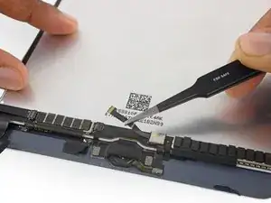
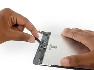
Desolder the six solder pads from the lower left of the display to remove the sensor assembly cable.
-


To reassemble your device, follow these instructions in reverse order.

4 comments
Not only is that part in step 39 crucial to Smart-Cover function, but the regular sleep/wake function will not work if this isn’t transferred. Wish the replacements were shipped with this part attached, because soldering those tiny points is near impossible to do! Buyer/repairer beware.
Its better to have reassemble instruction, like where i am going to put the new adhesive?
The iFixIt replacement part did not come with adhesive, so I had to reuse the old adhesive that got pulled and torn during removal of the bad screen.
Also, the iFixIt replacement part does not come with the sleep/wake sensor (Step 39). Following my repair, the iPad is no longer capable of going to sleep (neither by the button on top nor through AssistiveTouch), so we have to resort to waiting for the lock screen timer to turn the screen off whenever we’re done using it. I feel the soldering that is required to maintain this functionality (I would imagine it would need a millimeter-diameter drop of solder on six contacts that are then pressed together with the transplanted part to form the bond without solder spilling onto a neighboring contact) is not within the capability of most casual repairers.
If I were to do this repair again, I would find a part that has fresh adhesive and the sleep/wake sensor already attached.
Unfortunately, you only know you have inserted it too far when you have, and you start seeing little bubble veins form between the glass screen and the LCD.
The adhesive can be very stiff/hard, and if pushing through it can result in the pick plunging into the LCD when the adhesive finally gives way.
Take your time, use alot of heat, and if you need to try and push the pick in, try and do so in a slicing motion along the edge, use the wide edge, or hold the pick so that your finger will hit the edge of the screen before the pick tip will pass the bezel.
lucanos -
Adhesive strips are only 1mm wide on sides. Up to 5mm wide top and bottom. I used the Isclack. Screen seemed ok bending without breaking. Worth looking for a photo of the replacement adhesive strips so you know what you have to separate. Be extra careful at the lower right corner where the cables are.
ian cheong -
This is a failure of a guide as it doesn’t tell you to insert at a downward angle so you don’t potrude into the LCD… Now I have to spend more money to replace the screen as I pushed adhesive between the LCD and the screen even though I went no farther than a millimeter short of the screen...
Alec -
can you open the right side if the left is too cracked to use a suction cup on?
clark overhiser -
This guide needs amending urgently.
You MUST NOT put the pick or whatever you are using more than 2mm under the sides of the screen, or you will cut through the adhesive tape securing the backlight assembly to the LCD glass.
This will push adhesive into the viewable area of the LCD and cause the backlight assembly to no longer be secured against the LCD fully.
I now need a new screen.
This line below from the guide is absolutely INCORRECT and will ruin your expensive display:
”Don't insert the opening pick any deeper than the black bezel on the side of the display.”
The black bezel is 5mm to 6mm wide; you MUST NOT insert anything to that depth or you will destroy your display. 2mm maximum!
jamesqb2001 -
thanks. will take this into account for my repair
Adab Abu -
I too damaged my display because of this absolute nonsense (The German version, which I used, still had this INCORRECT portion in it). I can't believe how long it took iFixit to update this, even though people have been reporting this for years on end. Sadly iFixit still haven't updated a variety of other things that are still at the very least high risk instructions. I just messaged them the other day, but they don't seem to care about or understand the remaining issues that this guide has. At least they updated one of the most severe things, but they just plainly told me 'I'm wrong' about the rest. I liked iFixit it so far, and I've worked on a variety of (difficult) repairs - but this experience was a very huge let down.
Mac Stevenson -
A few thoughts after opening a number of Mini 4’s.
1) if the display is warm enough you can squeeze the digitizer and LCD back together after a minor incursion with the opening pick and it will reseal.
2) I’ve started going in at the top just to the right of the camera (I use an iFlex to get in then switch to a pick). Then I run down either side with my fingers choked up on the pick so there only a mm or 2 sticking out. Usually after running down one side, I can get the display open enough to get the pick in behind the LCD when I do the other side
Stow -