Introduction

This is a prerequisite-only guide! This guide is part of another procedure and is not meant to be used alone.

  1. VqcjPNEaoVZroUUX
    VqcjPNEaoVZroUUX
    oxLlt2g4CMIA12NV
    • The LiDAR sensor assembly is paired to the Face ID hardware. You'll need to transfer it to your replacement screen to keep Face ID functionality. The following steps show how to remove the sensor assembly and install it on your replacement screen.

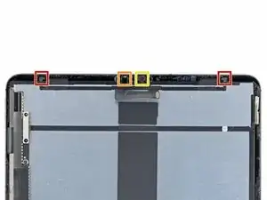
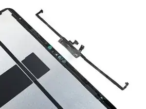
    • The LiDAR sensor assembly is composed of four total sensors:

    • Two ambient light sensors

    • One proximity sensor

    • One microphone

    • You'll need to separate each sensor from the screen before removing the entire assembly.

  2. u5C3BRJgFnqN3WIw
  3. iGVXOgT1MRNPhKAw
    iGVXOgT1MRNPhKAw
    1JitKLEEdZQCUj1u
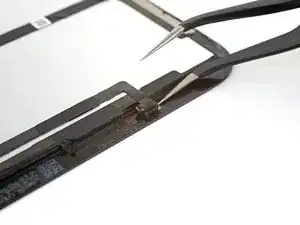
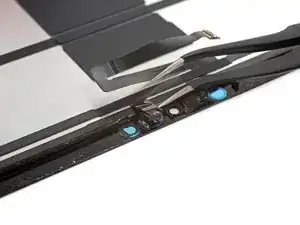
    • Insert one arm of your angled tweezers between the ambient light sensor and the screen.

    • Pry up to separate the sensor from the screen.

    • This might take significant force.

    • Repeat this procedure for the other ambient light sensor.

    The ambient light sensor system is constructed with a few component parts arranged in layers starting with its connection cable down to the last part that is attached to the glass.

    It is not super clear from the photos/instructions between which layers we need to pry to separate the sensor from the part that touches the glass. I'd like to see a straight on view of the exposed layer.

    I think I ended up separating the ambient light sensors incorrectly; my exposed sensor layers don't look the same as those you see of the stock part for sale on this site. Those have that layer with the small circle, but the instruction photos here show that layer left attached to the glass.

    My FaceID doesn't work and I suspect it may be because of this mistake I made.

    Chong Lee Khoo -

  4. YiFNYvoSXvayqMsJ
    YiFNYvoSXvayqMsJ
    ZCd6BEIxjdgBc4EA
    WHyfa5NAlEtWyyIL
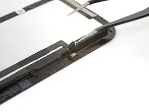
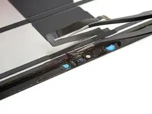
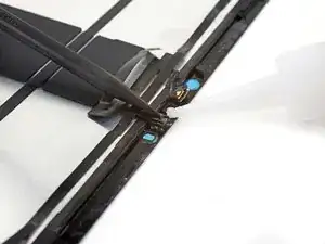
    • Insert one arm of your angled tweezers between the proximity sensor cable and the screen.

    • Slide the tweezers toward the screen while prying to separate the sensor from the screen.

    • This might take significant force and multiple iOpener heating cycles.

  5. 2oRBUiPlMVfj5pKv
    2oRBUiPlMVfj5pKv
    OQNseJyHwbkx4UcV
    • Peel off any tape covering the microphone.

    • Set the tape aside. You'll use it during reassembly.

  6. QviiEs5G2NsIdL2P
    QviiEs5G2NsIdL2P
    q11DmSQAyjsHFiNT
    wO4PD4Q2OyQxsxm4
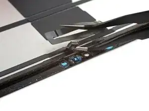
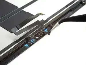
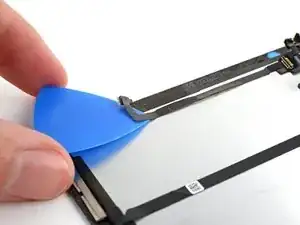
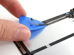
    • Slide an opening tool under the microphone to separate its adhesive.

    • Pry up to separate the microphone from the screen.

  7. jQQQwYT4hL1c2qtu
    jQQQwYT4hL1c2qtu
    PnscDrUADoJ1lriR
    yWIVuaDDxciI4dq4
    • Slide an opening pick under the LiDAR sensor assembly cable to separate it from the screen.

  8. FTXEEWMAUgbZNMEW
    FTXEEWMAUgbZNMEW
    UVdJT2xYVUfGoRUR
    T3jBiQcjvcioeDDT
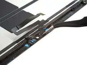
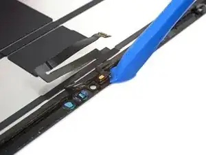
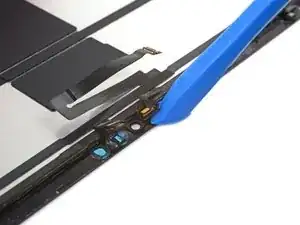
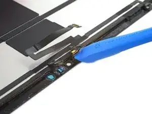
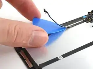
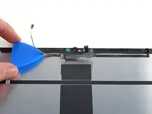
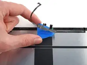
    • Continue sliding your opening pick under the LiDAR sensor assembly until it's completely separated from the screen.

    • Remove the LiDAR sensor assembly.

  9. iXJGhKwaMUsPJxMT
    • During reassembly, you'll have to perform the following:

    • Align the LiDAR sensor assembly on your replacement screen.

    • Use Tesa tape, or similar double-sided tape, to secure the cables to the screen.

    • Use E6000 adhesive, or similar adhesive, to secure the sensors to their cutouts on the screen.

    • Only apply adhesive to the edges of the sensors. Placing adhesive on the front will break them.

Conclusion

To reassemble your device, follow these instructions in reverse order.

Chayton Ritter

Member since: 21/08/20

17428 Reputation

0 comments