Introduction
Prereq for disconnecting all connectors from logic board.
-
-
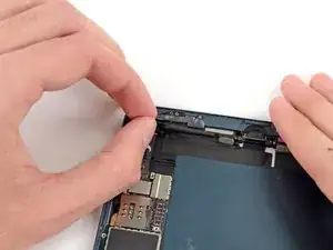
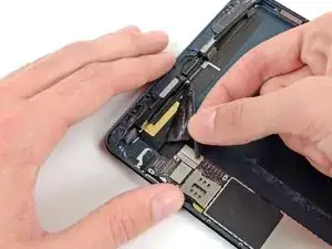
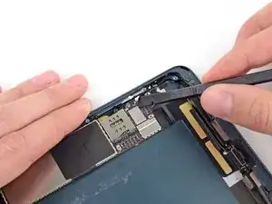
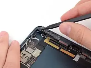
Use tweezers to peel up and remove the small piece of tape covering the front-facing camera cable connector.
-
-
-
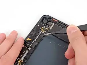
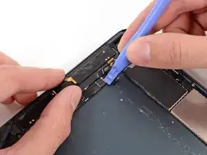
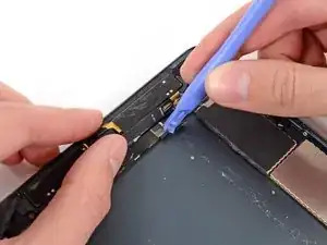
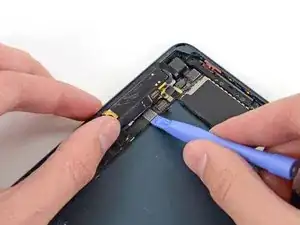
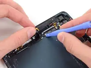
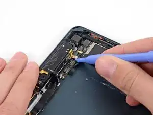
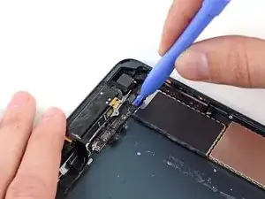
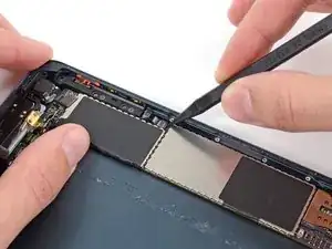
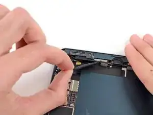
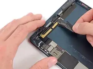
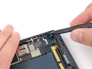
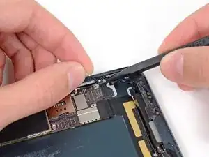
Use a plastic opening tool to gently pry the upper metal plate up from the front-facing camera cable connector.
-
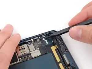
Being careful not to break the plate or the tape attached to it, pry it up and fold it away from the front-facing camera cable connector.
-
-
-
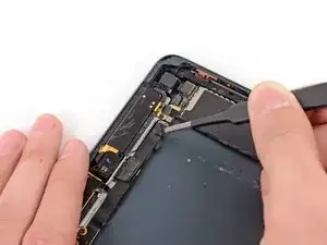
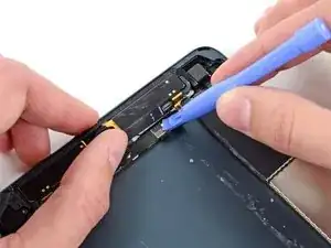
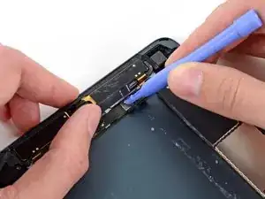
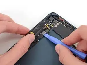
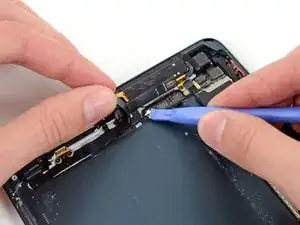
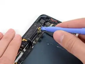
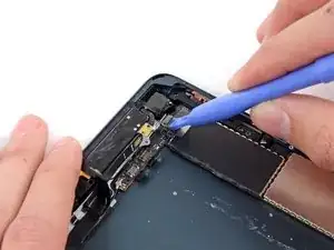
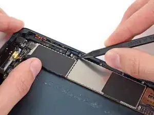
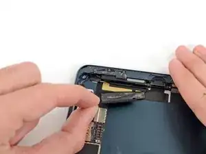
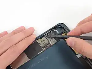
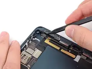
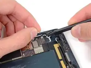
Gently pry the second (lower) metal plate up from the front-facing camera cable connector.
-
Again, carefully pry the plate up and away from the front-facing camera cable connector.
-
-
-
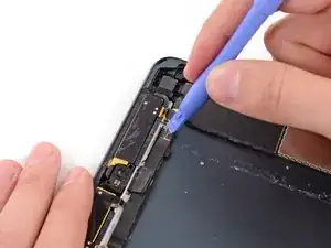
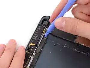
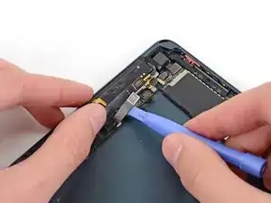
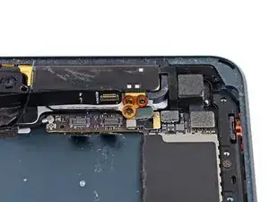
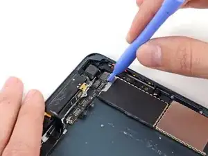
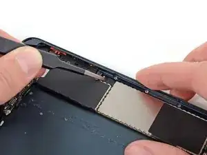
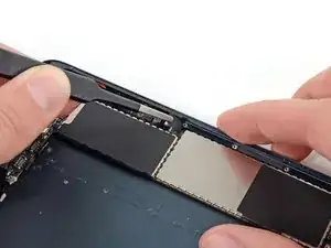
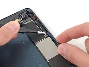
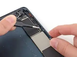
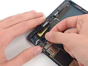
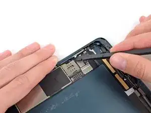
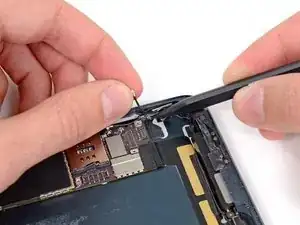
Use a plastic opening tool to pry the front-facing camera cable's connector up from its socket on the logic board.
-
-
-
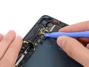
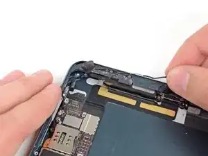
Use tweezers to peel up and remove the small piece of tape covering the headphone jack cable connector.
-
-
-
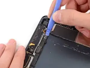
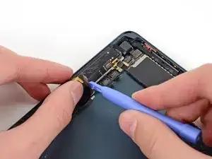
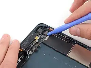
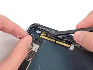
Use a plastic opening tool to gently pry the lower metal plate up from the headphone jack cable connector.
-
Being careful not to break the plate or the tape attached to it, pry it up and fold it away from the headphone jack cable connector.
-
-
-
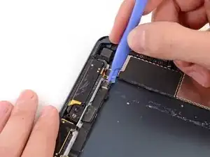
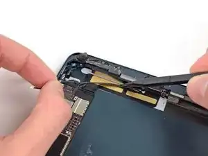
Pry the second (top) metal plate up from the front-facing camera cable connector.
-
Again, carefully pry the plate up and away from the headphone jack cable connector.
-
-
-
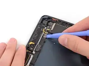
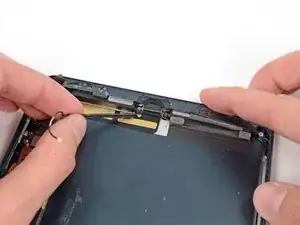
Use a plastic opening tool to pry the headphone jack cable's connector up out of its socket on the logic board.
-
-
-
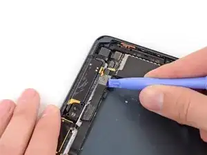
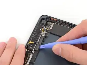
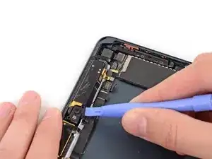
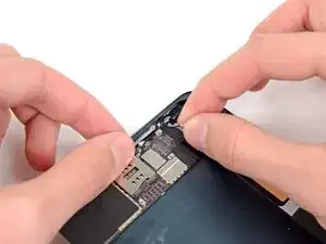
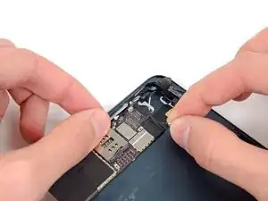
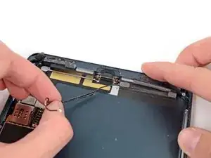
Use a plastic opening tool to pry the top left antenna cable up from its socket on the logic board.
-
-
-
Remove the following three screws securing the top right antenna to the rear case:
-
Two 1.3 mm #00 Phillips screws from the side of the antenna's socket.
-
One 1.8 mm #00 Phillips screw.
-
-
-
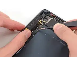
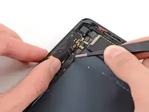
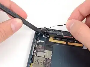
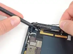
Disconnect the top right antenna's coaxial cable from the logic board with a plastic opening tool.
-
Gently bend the cable and screw tab up out of the way of the logic board.
-
-
-
Use a plastic opening tool to pry the rear-facing camera cable up from its socket on the logic board.
-
-
-
Pry the top right antenna's ribbon cable up from its socket on the logic board with a plastic opening tool.
-
-
-
Use tweezers to peel up and remove the small piece of tape covering the button ribbon cable ZIF connector.
-
-
-
Use tweezers to pull the button ribbon cable straight out of its ZIF socket on the logic board.
-
-
-
Use the flat end of a spudger to disconnect the two bottom antenna cable connectors from their sockets on the logic board.
-
-
-
Use the tip of a spudger to peel back the small piece of tape covering both antenna cables on the bottom right side of the iPad.
-
-
-
With the tip of a spudger, peel up the larger piece of tape covering both antenna cables near the bottom of the rear case.
-
-
-
Use the tip of a spudger to pry the small metal retaining clip off the left antenna cable, then de-route the cable from the clip.
-
-
-
Use the tip of a spudger to remove the small piece of tape securing the antenna cable in the bottom right corner of the iPad.
-
-
-
Use the tip of a spudger to pry the antenna cable tape up from the rear case of the iPad.
-
Gently pull the antenna cable out of the way as you work along the piece of tape, to keep it from resealing.
-

To reassemble your device, follow these instructions in reverse order.