Introduction
The purpose of this guide is to show where the LCD temperature sensor and cable are located so they can be replaced if necessary
Tools
-
-
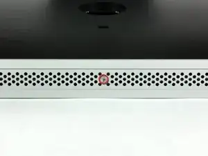
Loosen the single Phillips screw in the center of the access door.
-
Remove the access door from your iMac.
-
-
-
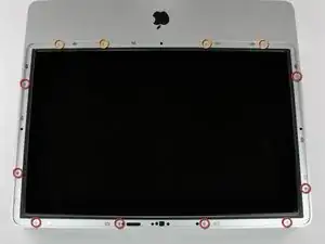
Remove the following 12 screws securing the front bezel to the rear case:
-
Eight 13 mm T8 Torx.
-
Four 25 mm T8 Torx.
-
-
-
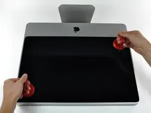
Place your hands at the top corners of the bezel (to the side) and lift the bezel 2-3cm from the body by working from the top. After this you can also disengage the bottom of the bezel (the memory modules will prevent the bottom of the bezel to detach first). When reassembling, start with the bottom of the bezel.
-
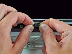
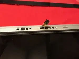
To fully detach the bezel: disconnect the microphone cable connector, removing tape as necessary.
-
To keep it attached, leave the microphone cable attached to the logic board, and place the bezel 'above' the chassis, with the microphone cable forming a hinge.
-
-
-
be sure to tuck the microphone cable and connector into the void next to the camera board.
-
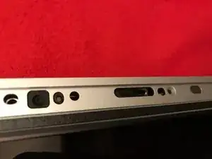
Gently guide the microphone connector and cables through the ±1in long slot at the right of the iSight camera. Once the bezel is properly assembled, gently push the microphone connector and cable into the bezel through that slot.
-
-
-
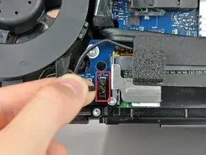
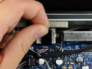
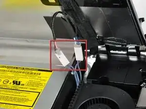
Pull the LCD temperature sensor connector straight up out of its socket on the logic board.
-
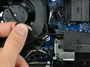
If necessary, de-route the LCD temperature sensor cable from behind the logic board.
-
-
-
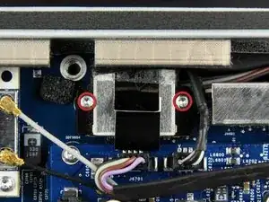
Use the attached black tab to pull the data display cable connector away from the logic board.
-
-
-
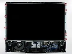
Remove the eight 12 mm T8 Torx screws securing the display panel to the rear case.
-
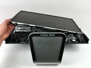
Lift the display panel from its left edge and rotate it toward the right edge of the iMac.
-
-
-
With the display panel still lifted, disconnect the four inverter cables.
-
If you are replacing a hard drive and have an extra set of hands, it is possible to reach in and remove the drive without disconnecting anything but the LCD temp and display connector in the previous step with the LCD in its propped position.
-
-
-
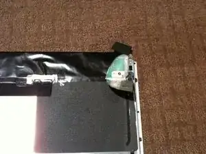
Lay the display panel face down on a cleared surface ensuring nothing is under the panel that may damage it.
-
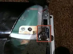
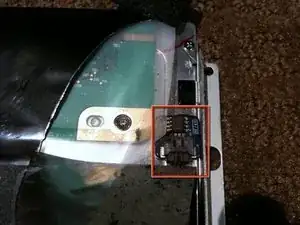
Gently peel the foam off the sensor to reveal the PCB assembly.
-
Disconnect the cable to remove the sensor
-
-
-
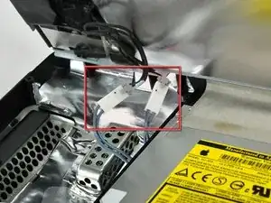
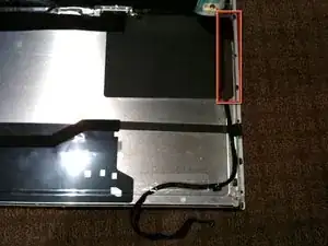
Note the routing of the cable. It runs up the right side of the display panel and under the edge of black plastic PSU guard adhered to the display panel
-
To reassemble your device, follow these instructions in reverse order.

isn't it actually pc2-5300s ?
grze -