Introduction
Replace a broken optical drive to read compact disks.
Tools
Parts
-
-
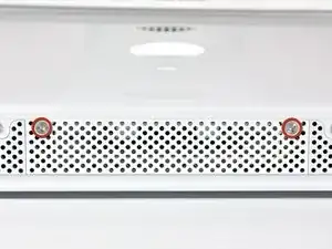
Loosen the two Phillips screws securing the access door to your iMac.
-
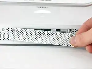
Remove the access door.
-
-
-
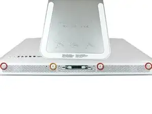
Remove the following screws along the lower edge of your iMac:
-
Three 6 mm T8 Torx screws
-
One 8 mm T8 Torx screw (Right side of the RAM slot on 2105)
-
-
-
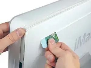
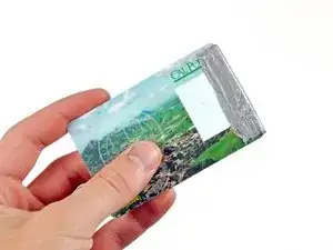
Insert a plastic card up into the corner of the air vent slot near the top of the rear case.
-
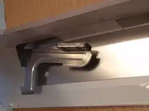
Push the card toward the top of the iMac to release the front bezel latch.
-
Pull the front bezel away from the rear case.
-
Repeat this process for the other side of the front bezel.
-
If the bezel refuses to release, try lifting the lower edge of the front bezel slightly away from the rear case (detailed in the next few steps) and repeat the latch release process.
-
-
-
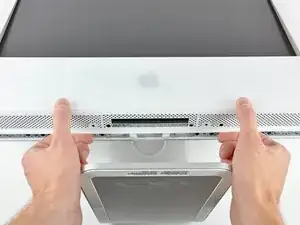
Lay your iMac stand-side down on a flat surface.
-
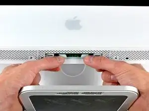
To lift the front bezel off the iMac, simultaneously:
-
Use your thumbs to press in the RAM arms and hold the iMac down.
-
Use your index fingers to pull the small bridge of material on the front bezel toward yourself.
-
Pull the front bezel up with your index fingers.
-
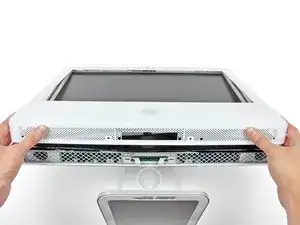
Once the small bridge of material has cleared the RAM arms, lift the front bezel by its lower edge just enough to clear the bottom edge of the rear case.
-
-
-
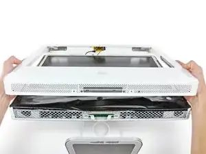
Lift the front bezel off the rear case and rotate it away from the bottom edge of the iMac, minding the camera and microphone cables still attached to its upper edge.
-
-
-
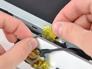
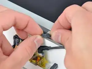
Disconnect the microphone cable.
-
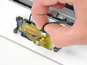
Disconnect the camera cable by pulling its connector away from the socket on the camera board.
-
-
-
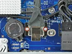
Remove the two 5 mm T6 Torx screws securing the display data cable connector to the logic board.
-
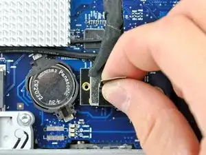
Pull the display data cable connector up off the logic board by its black pull tab.
-
-
-
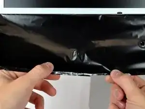
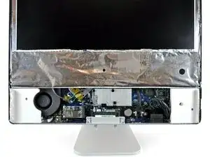
Allow the lower EMI shield to hang down from the display.
-
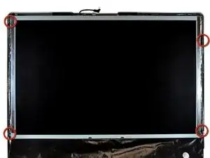
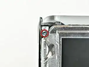
Remove the four 7.5 mm T10 Torx screws securing the display to the rear case.
-
-
-
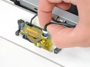
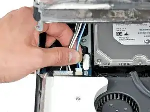
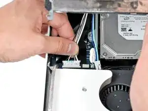
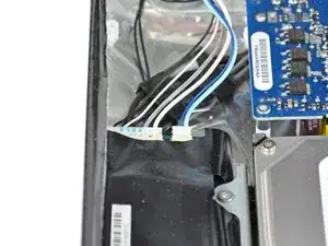
Disconnect the two inverter cables at the top edge of the inverter using the method explained in the previous step.
-
-
-
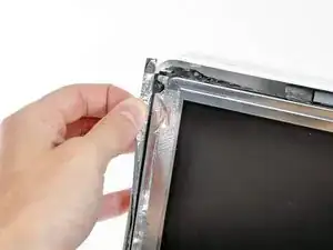
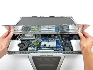
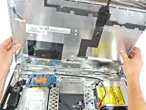
Rotate the display until it is nearly perpendicular to the rear case and lift it up to peel it off the EMI shield stuck to its top edge.
-
-
-
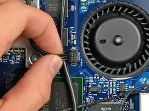
Disconnect the optical drive thermal sensor cable by pulling its connector away from the socket on the logic board.
-
-
-
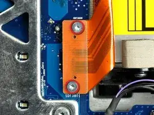
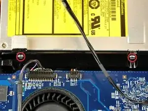
Remove the two 3.6mm T6 Torx screws securing the optical drive ribbon cable connector to the logic board.
-
-
-
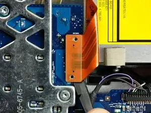
Use the flat end of a spudger to pry the optical drive ribbon cable connector up off the logic board.
-
Bend the optical drive ribbon cable back away from the logic board.
-
-
-
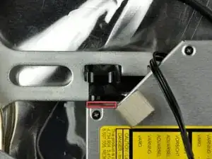
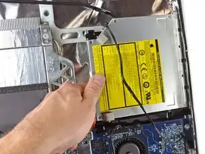
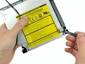
Insert the flat end of a spudger into the gap between the optical drive and its bracket until it contacts the chassis.
-
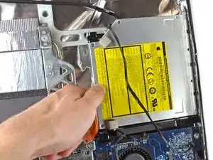
Grab the spudger as close to the surface of the optical drive as you can, then depress the release tab with your thumb while pulling toward yourself.
-
-
-
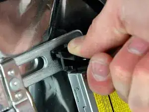
Reach behind the chassis and use your finger to unclip the lower optical drive tab from the chassis.
-
-
-
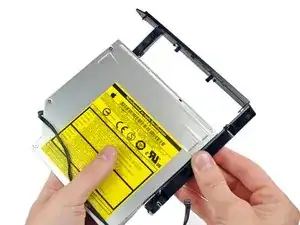
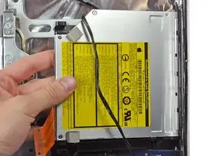
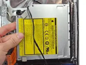
Maneuver the optical drive out of the rear case, minding the two plastic pins molded into the rear case near the open end of the optical drive that can break off.
-
-
-
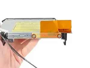
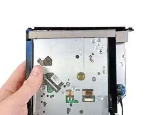
Insert the flat end of a spudger into the gap between the optical drive cable connector and the optical drive.
-
Twist the spudger to separate the connector from the optical drive.
-
-
-
Use the flat end of a spudger to remove the small pieces of EMI foam from the underside of the optical drive.
-
-
-
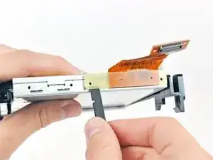
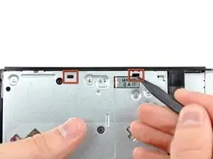
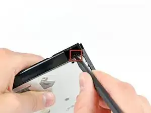
Use the tip of a spudger to push the two optical drive bracket tabs out of their slots in the top of the optical drive.
-
-
-
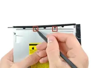
Using the tip of a spudger, press the optical drive bracket tab out of its slot on the side of the optical drive.
-
-
-
Use the tip of a spudger to press the optical drive bracket tabs out of the slots in the top of the optical drive.
-
-
-
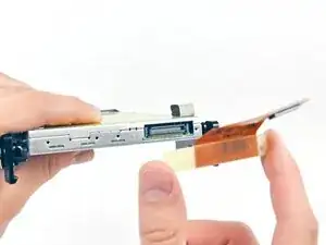
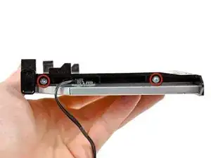
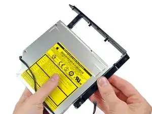
Pull the optical drive bracket toward the open end of the optical drive to free it from the optical drive.
-
-
-
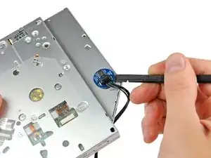
Use the flat end of a spudger to pry the optical drive thermal sensor off the adhesive securing it to the optical drive.
-
To reassemble your device, follow these instructions in reverse order.
4 comments
I cannot get the top latches to release.Tried all the suggestions here and on YouTube. Especially a good video from Twistedmac. Made his suggested access card all different ways but nothing is working.
Any further tips or help will be greatly appreciated.
Also on the latch picture where does the credit card actually have to make contact? Please help I'm going bonkers.
Finally figured it out. Lift up the bezel from the bottom about 45 deg
you will then see the latch on both sides. Put a spudger or whatever under the latch and push up. Do not lift the bezel too high or you will damage the latches. This worked like a miracle for me.
Had no success with the credit card method, it was really frustrating.
The sleestack post is also also great.
OMG!!! The rating for this repair as "moderate" is waaaaaayyyy off! I've been repairing various laptops for YEARS on iFixit and this was my first attempt at a desktop repair. It was so much more fidgety and difficult than the hardest laptop I've done (probably about 12 - 15 other repairs by now).
And sorry... tho' I love this site and am grateful for these tutorials, this one was wanting in detail and assumed that I not only knew terminology that I didn't know (I was able to figure it out of course, I DID finish the repair) but skipped important details that made it infinitely harder (and took me waaaayyy longer than it should have!). For example, when removing the optical drive, the guide skipped about three steps and I ended up accidentally breaking some delicate plastic bits. And gee thanks for waiting until I have everything apart to tell me I need a longer screwdriver! I found a tedious workaround, but... sheesh dude! All in all, I'd have to say...by far the WORST experience I've had on this site!
The credit card trick with the latches on the upper corners of the bezel works fine if you push the card in at 45 degrees, from the slot to the corners of the bezel. Works first time every time. The photo is deceptive.
Peter -

Swapping in a new CPU and an SSD took me about 10 hours. I did take a dinner break and spent another hour rooting around in my garage to find my thermal paste. Still, this procedure can take a long time.
gordonhamachi -