Introduction
Power hungry? Keep those electrons flowing by replacing your power supply.
Tools
Parts
-
-
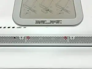
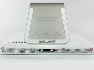
Loosen the two captive Phillips screws securing the access door to the iMac.
-
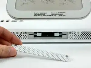
Remove the access door from the iMac.
-
-
-
Flip your iMac over and lay it stand-side down on a flat surface.
-
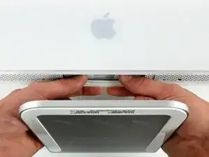
To lift the front bezel off the iMac, simultaneously:
-
Use your thumbs to press in the RAM arms and hold the iMac down.
-
Use your index fingers to pull the small bridge of material on the front bezel toward yourself.
-
Pull the Front bezel up with your index fingers.
-
Once the small bridge of material has cleared the RAM arms, lift the front bezel by its lower edge just enough to clear the bottom edge of the rear case.
-
-
-
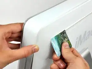
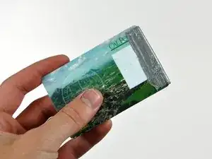
Insert a plastic card up into the corner of the air vent slot near the top of the rear case.
-
Push the card toward the top of the iMac to release the front bezel latch.
-
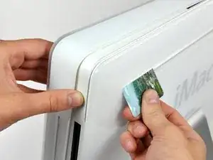
Pull the front bezel away from the rear case.
-
Repeat this process for the other side of the front bezel.
-
If the bezel refuses to release, try pressing the lower edge back onto the rear case and repeat this opening process.
-
-
-
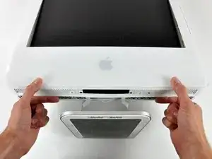
Lay your iMac stand-side down on a table.
-
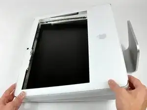
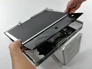
Lift the front bezel from its lower edge and rotate it away from the rest of your iMac, minding the RAM arms that may get caught.
-
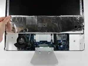
Lay the front bezel above the rest of the iMac.
-
-
-
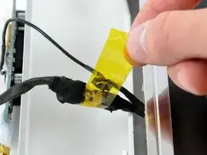
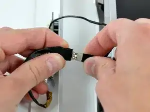
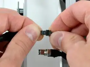
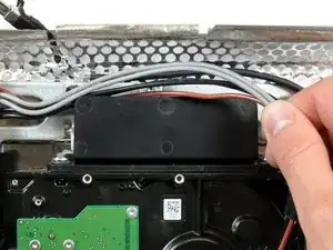
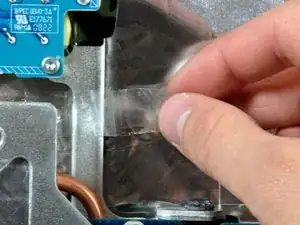
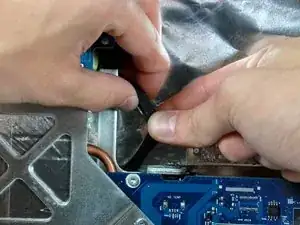
If necessary, remove the piece of kapton tape(it is ok to toss this) wrapped around the microphone and camera cables.
-
-
-
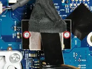
Remove the two 4.8 mm T6 Torx screws securing the display data cable to the logic board.
-
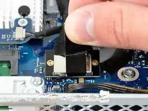
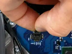
Grab the display data cable connector by its black tab and pull it straight up off the logic board.
-
-
-
Inverter cable on 24inch iMac pulls off to the left.
-
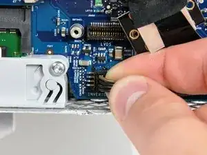
Pull the inverter cable connector straight up off its socket on the logic board.
-
-
-
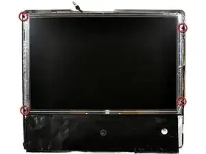
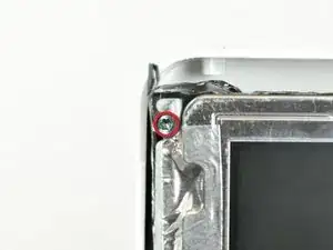
Remove the four 8 mm with 2 mm thick head coarse-thread T10 Torx screws securing the display to the rear case.
-
-
-
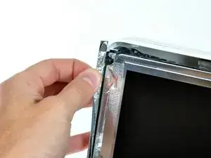
Lift the display from its lower edge and pull it toward yourself to peel off the EMI shield attached to its top edge.
-
-
-
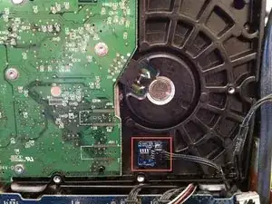
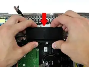
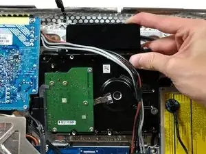
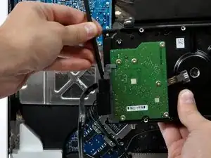
Press the hard drive bracket down to free it from the rear case, then rotate the top of the drive toward yourself.
-
-
-
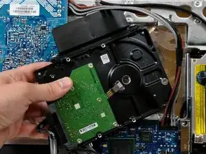
Lift the hard drive off its lower pins and pull it out of the rear case, minding the power supply cables that may get caught.
-
-
-
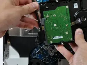
Insert a spudger between the SATA connectors and twist it to separate the connector from the hard drive.
-
Disconnect both SATA connectors.
-
-
-
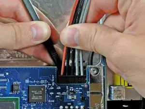
Unplug the power supply cable bundle from the logic board by simultaneously depressing the locking mechanism (toward yourself) with a spudger and pulling the connector away from its socket.
-
-
-
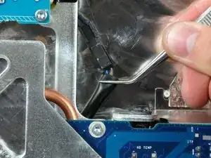
Use a pair of tweezers to pull the AC-in cable out from underneath the chassis.
-
Disconnect the AC-in cable by simultaneously depressing its locking mechanism and pulling the connector away from its socket.
-
-
-
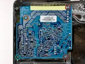
Remove the four T10 Torx screws securing the power supply to the rear case.
-
Two 14mm fine-thread screws on the right.
-
One 14mm coarse-thread screw in lower left corner.
-
One 20mm coarse-thread screw in upper left corner.
-
-
-
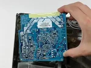
Lift the power supply out of the rear case, minding the AC inlet cable that may get caught on the chassis.
-
To reassemble your device, follow these instructions in reverse order.
5 comments
It was quite easy, but a little fiddly. I didn't need to remove the hardrive to replace the power supply.
The PSU in the 17” is smaller than shown and has the DC - DC convertor above it.
DC - DC convertor is above the psu in the 17” model and the psu is half the size than that shown.

That is a really, really unnecessarily complex way of fitting a new hard drive. Thanks, but no thanks...
annax -