Introduction

Replace your inverter board with this guide.

  1. ZmbcJOeMcMf6nt5J
    • Lay the iMac display-side down on a flat surface.

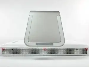
    • Loosen the three Phillips screws securing the rear panel to the iMac.

    • These screws are captive in the iMac. The center screw will stop turning after about 3.5 turns and the outer screws will stop turning after about 5.5 turns. Do not try to remove these screws from your iMac.

    My iMac has only ONE catch, the central one, so the two outer screws are not to be touched.

    In fact, I tried so hard to unscrew them, with a good screwdriver, that my hand hurt. Knowing that some times captive things (like these screws or a faucet) can be already at the end of their travel and we only lock them further into that position, I tried both screwing and unscrewing to no avail.

    paulfrancoeur -

    The two outer screws each drive a locking bar that engage tabs on the rear panel.

    They definitely need to be unscrewed.

    Dale Stanbrough -

    That chick MJ is sexy!!!!!

    djmadcracker -

    Looks like one of these screws is not like the others... a security Philips?! Never seen one of those before.

    Terry Mullane -

    Please Note: If your iMac has an antenna for the airport extreme and not the bluetooth card. Don't buy the bluetooth get the airport extreme instead. Also, some newer devices may not work with these units.

    James Janota -

    Just want to say thank you to ifixit! You guys are amazing and so helpful! This was so easy to do and I ordered the part I needed as well! We are up and running over here and my 7 year old son could not be any happier! Thank you!

    mary nicolazzo -

    These are the easiest way to resolve the Wireless connectivity at my home. Thanks ifixit for sharing this.

    Geek Squad -

  2. CXXvGbeo2PYwhMNV
    CXXvGbeo2PYwhMNV
    qvDGtVsUUxTXMTvI
    Hs3JDgtjpSPjgMqC
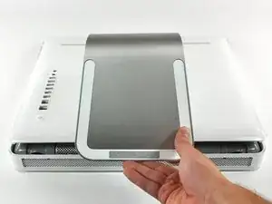
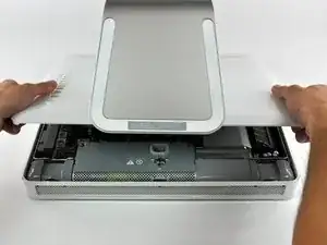
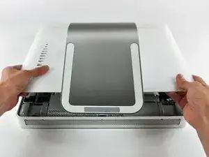
    • Lift the rear panel slightly from the bottom edge of the iMac.

    • Pull the rear panel toward yourself and remove it from the iMac.

  3. cxIXjOJc2JWNyurc
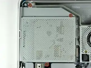
    • Remove the three 8 mm brass Phillips screws securing the optical drive to the midplane.

  4. ogRcLKxEFHAJyHX2
    ogRcLKxEFHAJyHX2
    dmw3qTBQoCfkC2ZS
    or2wE1EpcqPCZXgw
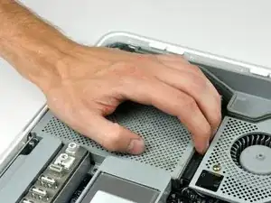
    • Lift the optical drive near the connector to separate it from the logic board.

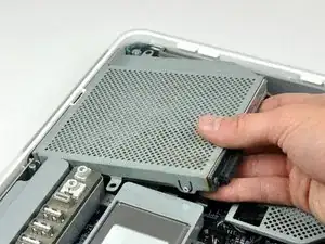
    • Lift the free end of the optical drive just enough to clear the fan cover. Lifting the free end of the optical drive too far may break the plastic positioning pins off the front bezel.

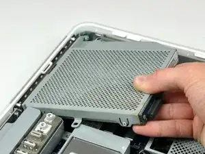
    • Lift the free end of the optical drive slightly, then pull it away from the edge of the rear case to clear the two plastic positioning pins.

    • Lift the optical drive out of your iMac.

    • When reinstalling your optical drive it may be necessary to set the bezel attached to the open end of the drive on the plastic positioning pins molded into the front bezel of the iMac and pull the connector side of the drive toward the edge of the rear case, bending it outward slightly, to properly seat the connector.

  5. hsK2hFMvXAqMwSW6
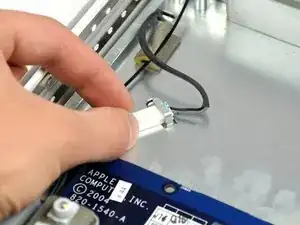
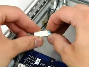
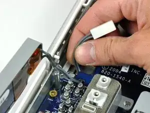
    • Slide the inverter-to-display cable connector from under the metal clip on the midplane.

  6. sVQeYXQfGRsRLFZF
    • Disconnect the inverter-to-display cable connector by pulling it straight away from its socket.

  7. kdRxbAtNuFcNLEKJ
    kdRxbAtNuFcNLEKJ
    ktGT6iG2u6sINjWW
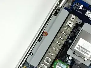
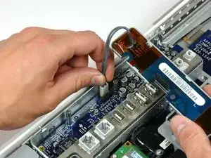
    • Remove the single Phillips screw securing the inverter to the logic board.

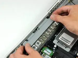
    • Lift the inverter straight up off the pins on the logic board.

    • Be sure to lift the inverter straight up off the logic board, as the connector pins are very long and easily bent. If the pins bend during removal, use the connector on the inverter as a guide to bend them straight.

  8. vBgrRUsdFJIhjJKS
    • De-route the inverter cable connector from the channel in the logic board.

  9. 4AGJSLkqAJu4eTdb
    • Disconnect the inverter cable from the logic board by pulling it straight up from its socket.

    • Replacement note: it may be helpful to carefully reattach this connector before seating the midplane assembly, making sure the connector safely passes through the hole in the midplane assembly.

  10. NnW1UBbRvyTlgFmH
    NnW1UBbRvyTlgFmH
    ZIrTLRSCUXbywwrK
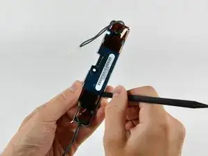
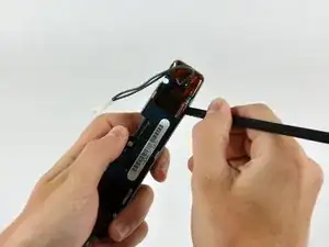
    • Insert the flat end of a spudger between the plastic inverter cover and the inverter board.

    • Run the spudger along the edge of the inverter board to free all the tabs holding the plastic inverter cover to the inverter board.

  11. yDdiAlebhU4vefSj
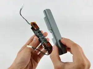
    • Lift the plastic inverter cover off the inverter board.

Conclusion

To reassemble your device, follow these instructions in reverse order.
Andrew Bookholt

585795 Reputation

0 comments