Introduction
Is the touch sensor screen not responding to any of the tricks you’ve tried? This guide will help you in replacing the touch sensor(s). You will need a Phillips #1 screwdriver.
-
-
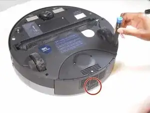
Depress the tab on the side of the dustbin to disengage its latch. It is spring loaded and will partially pop out. Remove it from its housing.
-
-
-
Flip the bObsweep over and remove the main brush’s screw (13.7mm Flat) with a flathead screwdriver.
-
Lift and remove the main brush and its plastic bearing end cap.
-
-
-
Remove the two screws (9.9mm Phillips #1) next to the rotating front wheel.
-
Remove the two screws (9.9mm Phillips #1) below the wheels on either side of the dustbin compartment.
-
Remove the screw (9.9mm Phillips #1) to the side of the brush motor.
-
Remove the screw (9.9mm Phillips #1) inside the brush compartment.
-
-
-
Carefully hold the top and bottom halves together and flip the bObsweep upright.
-
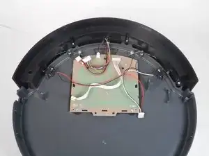
Lift the cover to reveal the mainboard.
-
-
-
Depress the tabs on the circuit plugs and lift them directly upward to remove:
-
The multicolored nine-wire circuit plug at the top edge of the board.
-
The red and black wire circuit plug directly next to it.
-
The seven white wire circuit plug on the bottom edge of the board.
-
The red, white, and black wire circuit plug on the bottom left corner of the board.
-


To reassemble your device, follow these instructions in reverse order.