Introduction

Prerequisite-only guide! This guide is part of another procedure and is not meant to be used alone.

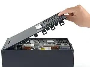
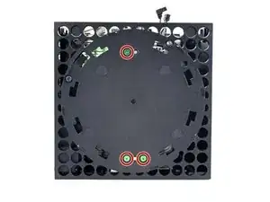
Use this guide to remove the center chassis assembly from the plastic shell on an Xbox Series X.

  1. 3bZJo5AEqOISmVxU
    3bZJo5AEqOISmVxU
    kGOaBCslJWZrcPUf
    • Before you begin, completely power down and unplug all cables from your console.

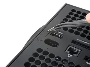
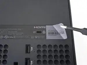
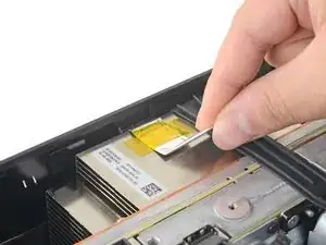
    • Use a pair of tweezers to remove the sticker hiding the first screw on the back panel, near the base.

  2. QVtqrbDsBgrw6WZq
    QVtqrbDsBgrw6WZq
    IVS6BushCHXDMTuP
    wWNRqGPUqtlhrNV2
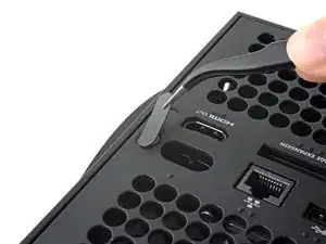
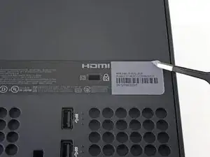
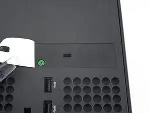
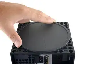
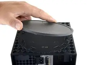
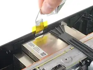
    • Use a pair of blunt tweezers to peel back the large sticker on the back panel to reveal the second screw.

    • You only need to peel this sticker to where you can access the hidden screw. You don't need to pull it completely off.

    • Technically, these are tamper-evident stickers, but don't worry—Microsoft can't legally void your warranty, as long as you don't damage anything. Have fun!

    Recommend using a hair dryer to soften the label adhesive.

    Crash -

    Microsoft can void your warranty. They can use whatever excuse if it is sent in because you opened it and you cannot prove you didn’t damage it.

    DirtyD -

  3. aqjZt2Xb3m3aolZQ
    • Use a T8 Torx driver to remove the two 7.4 mm-long screws securing the back panel.

    • Throughout this repair, keep track of each screw and make sure it goes back exactly where it came from to avoid damaging your console.

  4. m4ius4PHhbf1vBgc
    m4ius4PHhbf1vBgc
    dAiRHFUnRejZqcLE
    IbXFLL4MqqboGYqR
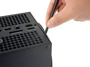
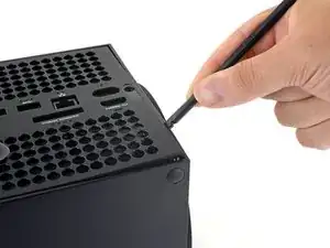
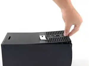
    • Insert the flat end of a spudger into the gap between the back panel and the shell, near the left side of the base.

    • Pry up the back panel to release it from the locking clips.

  5. v3nCqkOqZPiQPTiV
    v3nCqkOqZPiQPTiV
    enZdeM2q3kplUM35
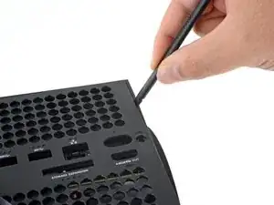
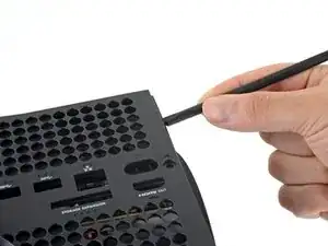
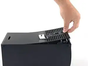
    • Insert the flat end of a spudger into the gap between the back panel and the shell, near the right side of the base.

    • Pry up the back panel to release it from the locking clips.

  6. T3KZEDU3kapNSLob
    T3KZEDU3kapNSLob
    dTuJey3MhNX4153H
    3Uhf3MV2ssejZD2H
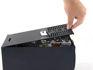
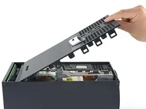
    • Grip the back panel at the opening you just created and pull it up and away from the shell to unclip the long edges.

    • During reassembly, press along the edges of the back panel to snap it into place.

  7. uldRdnlZxZAALgGC
    uldRdnlZxZAALgGC
    LL1Kmc3SnuUNCMOg
    cxQDaTGO2Zcg2IFW
    • The back panel slots into a gap at the top of the shell.

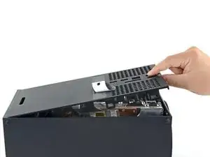
    • Tilt the back panel up and pull it away from the top edge of the shell to release it from the gap.

    • Remove the back panel.

  8. s5HXWZ15bUqFvXiV
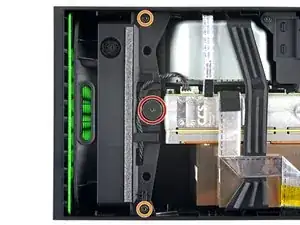
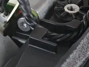
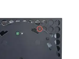
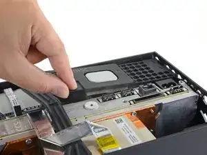
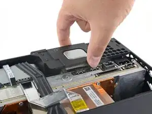
    • Use a T8 Torx driver to remove the three screws securing the fan to the center chassis:

    • One 10.5 mm pancake screw

    • Two 8.8 mm screws

    are there any 10.5mm wide head screw for the xbox fan for sale because i need a replacement because i accidentally broke mine

    GhostMindX9 -

  9. IPQZ2JOW6g3mq6yw
    IPQZ2JOW6g3mq6yw
    dDipWLCFPsWOO3Qq
    s5TfshEoqJTMEWXb
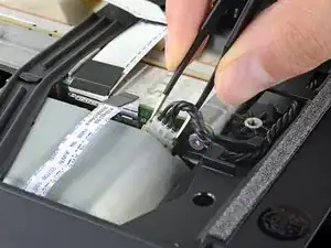
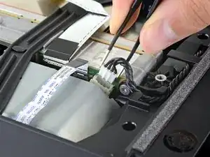
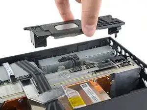
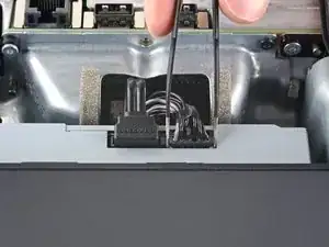
    • Use your fingers or a pair of blunt tweezers to grip the edges of the fan cable connector, and pull up to disconnect it from the center chassis.

    • Always pull cables by their connectors and not the wires themselves.

    • During reassembly, route the fan cable underneath its small cable guide on the fan housing so it doesn't interfere with the back panel.

  10. 32I1KI24pY3JZu4k
    32I1KI24pY3JZu4k
    LWIG3ECKkFoVTfRt
    • Slide the fan out of its slot to remove it.

    • During reinstallation, note that the fan can only be installed one way—make sure Master Chief is facing you.

    • If you are replacing the fan, a new fan will probably not include the plastic installation bracket. The bracket is attached to the fan with four T10 Torx screws. This is not pictured in this guide.

  11. TeS1w2jBIiJyJ5tC
    TeS1w2jBIiJyJ5tC
    GBcGsYAAuvqUAZFE
    MjvRJVRGOvIri4t6
    • Use the flat end of a spudger to lift up on the locking tab holding the base to the shell.

  12. N5ypbFiuFLLgCRbP
    N5ypbFiuFLLgCRbP
    SvsN3qWZdXACBrlc
    MfVUqOiHMbDUfFb5
    • Grip the base and rotate it counterclockwise to unlock it from the shell.

    • You may need to hold the locking tab open while you get the base started.

    • Remove the base.

    • During reassembly, drop the base tabs into their holes on the shell and twist clockwise until the base snaps into the interior locking tab.

    • When locked in place, the "Hello from Seattle" line will be parallel with the device's sides.

  13. WCybWp1L2MMPSGZ3
    WCybWp1L2MMPSGZ3
    re5IVejujiRDrS1l
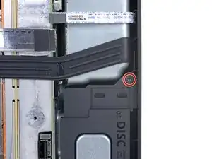
    • Use a T8 Torx driver to remove the two 8.8 mm screws securing the optical drive's vibration isolator to the shell: one on the base and one on the top of the isolator.

  14. Sv4TqfXBjJZ6SbRH
    Sv4TqfXBjJZ6SbRH
    KK1xoHxekFkfFF4m
    5rqMYEVtOxgVyGeJ
    • Lift up the optical drive's vibration isolator to remove it.

    • The vibration isolator grips the sides of the optical drive with silicone pads, so you may need to "walk" the isolator off of the drive to slip it off each side.

    • During reassembly, ensure the vibration isolator is pushed down and around both edges of the optical drive, so it sits flush with the rest of the center chassis.

  15. CuDAfMsFFYR4hvEI
    CuDAfMsFFYR4hvEI
    1ZM1OpOHMG6rvTHp
    6nmdPY3SVdBaAHVU
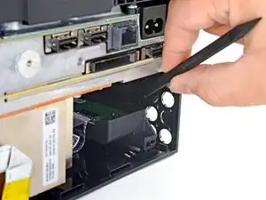
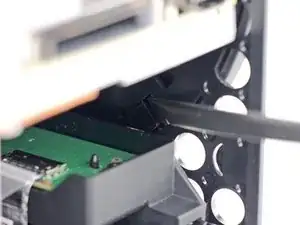
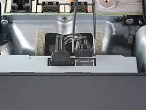
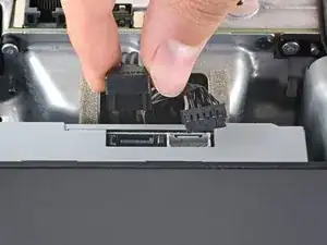
    • Use a pair of blunt tweezers to grip the edges of the optical drive power connector and pull up to disconnect it from the optical drive.

    • Always pull cables by their connectors and not the wires themselves.

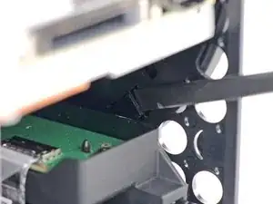
    • Use your fingers to pull up and disconnect the data cable from the optical drive.

  16. wM13ZRag2JLuhebq
    wM13ZRag2JLuhebq
    aHGUfCTjqFMty3f2
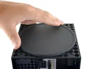
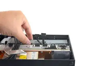
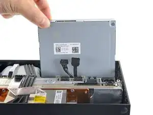
    • Grip the top edge of the optical drive and pull it out of its slot in the shell to remove it.

    • During reassembly, align the pegs on the bottom edge of the optical drive with the guide holes on the bottom of the shell.

    • If the drive is misaligned, the top vibration isolator will not be able to be installed correctly, and the disc reader will be misaligned with the front of the console.

  17. JThLNufCC5TuxZGO
    JThLNufCC5TuxZGO
    iDoNjhi3S2Tt1bY2
    PiESWahhDgT3noij
    • The ribbon cables and their connectors are extremely fragile, so always open locking tabs gently and pull cables slowly.

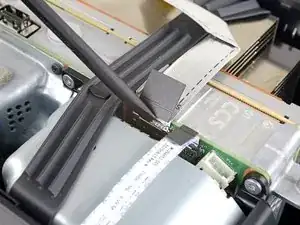
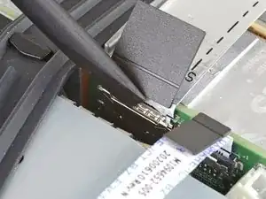
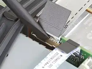
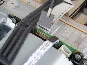
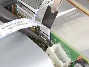
    • Use the flat end of a spudger to flip open the metal locking tab on the USB port ribbon cable.

    • During reassembly, gently snap the metal locking tab back into place once the cable has been inserted.

  18. reQaG4PGLwSMrQSa
    reQaG4PGLwSMrQSa
    CBr1rFORlKfRrMYn
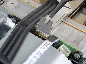
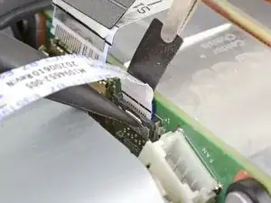
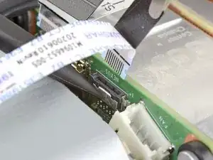
    • Use a pair of tweezers to pull up on the black plastic pull tab to disconnect the USB port cable.

    • Pull only on the pull tab, not the cable itself.

    • If the USB port cable feels adhered to the metal chassis, apply an iOpener or carefully heat it with a hair dryer to soften the adhesive.

    Connector i-pex Evaflex 5-HD 24 pin

    20952-024e-02

    http://www.i-pex.com/sites/default/files...

    drops206 -

    The silver ribbon cable is glued down to the center chassis, so only pulling on the black plastic pull tab will result in it pulling free from the cable as that tab is only glued to the cable.

    Better to heat the silver ribbon cable's adhesive with a hair dryer, separate the cable from the center chassis, and then pull the cable from the connector using the black plastic pull tab.

    Crash -

  19. CW421D6MGHTlbFdZ
    CW421D6MGHTlbFdZ
    rHN4vD2UGeuUT6BS
    nnCD6TpLq3CurvBs
    • Use the pointed end of a spudger to depress the metal tab on the side of the power button cable's board connector.

    • With the metal tab depressed, use a pair of tweezers to pull up on the pull tab to disconnect the power button cable from the center chassis.

    • Pull only on the pull tab, not the cable itself.

    • Don't pull on the cable without depressing the metal tab, otherwise you risk damaging either the cable or the connector.

    • During reassembly, the cable should lightly "snap" into place when inserted.

    I broke this connector during disassembly. Is there a part number I can use to get a replacement on Mouser or Digikey?

    Peter LeCraw -

    I broke this connector during disassembly too. Where can I get this connector?

    Oscar Cedeño -

    the manufacturer of connectors in series x is I-PEX.  exact part number (as far as I'm not mistaken) 20535-010E-02 EVAFLEX 5-VS.  0.5mm pin spacing (10pin connector). a possible rescue may be to desolder the connector from the switch board and solder it permanently there.

    http://www.i-pex.com/sites/default/files...

    drops206 -

    How do I purchase this from their website?

    munirbisharat12 -

    I have these connectors. Baycroc@fedtel.net

    Evenson Electronics -

    Would we be able to order them from you directly

    bailey jackson -

    Yes would we be able to order these connectors directly from you?

    Blake Roan -

    XSX NEXUS FPC Socket

    kasynlife -

  20. mRjpYsIcQtO1VZSR
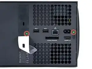
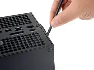
    • Use a T8 Torx driver to remove the three 7.4 mm screws securing the center chassis assembly to the shell.

  21. BG1mV12jbtdhWuqh
    BG1mV12jbtdhWuqh
    CdanjTj5YnExFJQ6
    • Gently peel the taped USB port ribbon cable off of the heatsink.

  22. FlZxtfQKAsehwPZS
    FlZxtfQKAsehwPZS
    b2mITSOoDXR14Vbx
    vRsFH3BGMFfUPM5w
    • The center chassis is aligned to the shell with guide pegs. These pegs will need to slide out of their slots to allow the chassis to be lifted out.

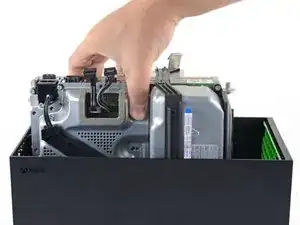
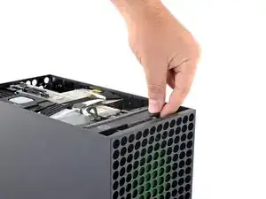
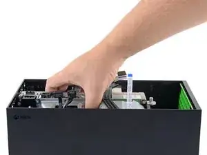
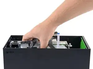
    • Grip the center chassis and pull it towards the green fan grille at the top of the shell, uncoupling the guide pegs from the shell.

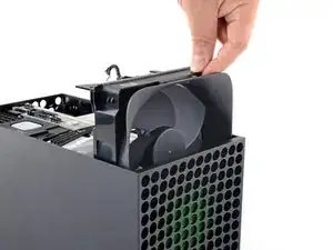
    • Lift out the center chassis assembly to remove it from the shell.

    • During reassembly, make sure neither of the ribbon cables get pinched as you lower the center chassis into the shell.

Conclusion

To reassemble your device, follow these instructions in reverse order.

Carsten Frauenheim

Member since: 10/03/20

110978 Reputation

0 comments