Introduction
-
-
-
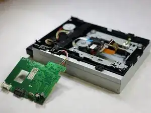
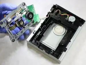
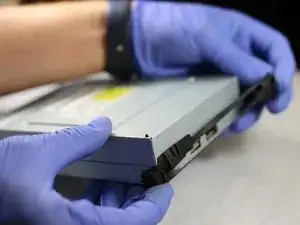
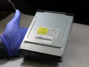
In order to get to the laser to replace it you first have to remove the disk drive.
-
The link at the top is an IFIXIT guide that helps you to remove and replace the optical disk drive.
-
-
-
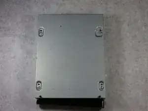
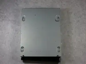
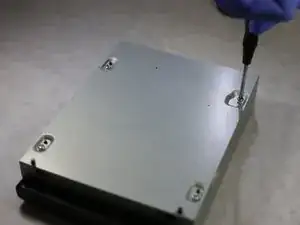
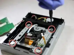
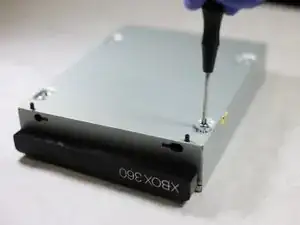
With the underside exposed, identity the 4 main screws.
-
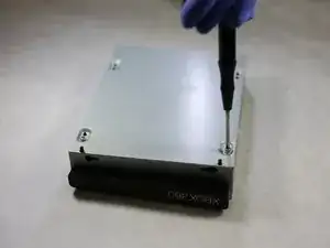
Remove these 4 screws.
-
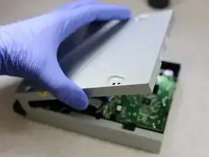
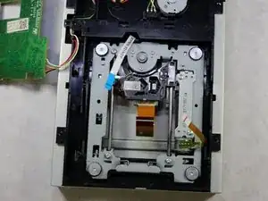
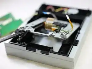
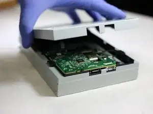
Remove the cover to expose the assembly
-
-
-
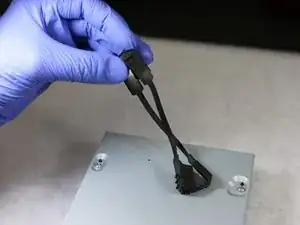
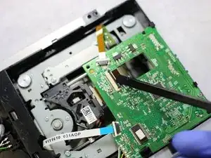
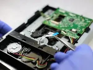
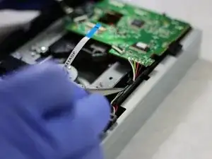
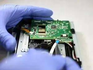
Locate the three ribbons connected to the board.
-
Use the plastic spudger to unclamp the ribbons from the board.
-
-
-
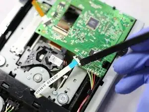
The ribbons will now be able to slip out. With the tweezers, gently pull the ribbons to completely detach them.
-
-
-
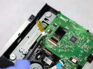
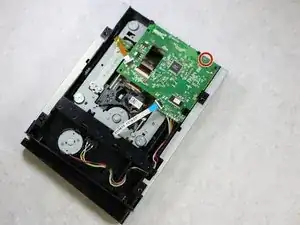
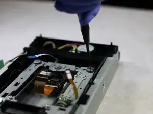
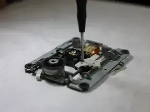
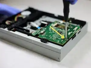
Locate the screw that holds the motherboard to the disk drive
-
Using your screwdriver, remove the motherboard screw.
-
-
-
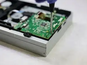
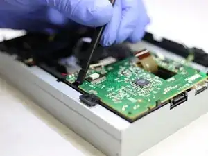
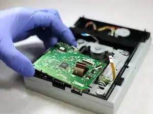
Use the spudger's flat side to get under the biggest plastic pin on edge of the board.
-
Push the pin backwards and off of the board.
-
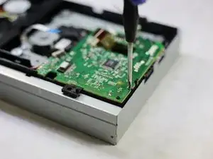
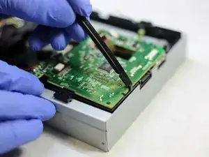
Using your spudger again, push the second smaller pin backwards and off of the board.
-
Then, slide the board away from the pin slightly to be free of the last plastic element (the black corner thing).
-
-
-
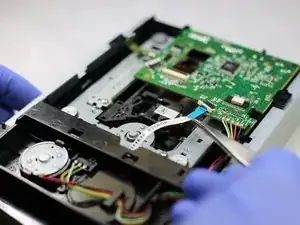
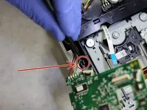
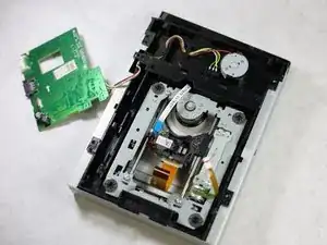
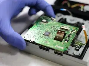
With the board freed from it's trappings, locate the pin securing the wires connected the board.
-
Use your spudger to press this pin backwards.
-
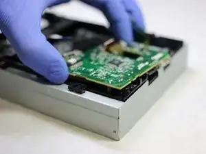
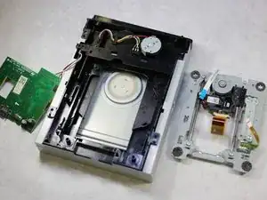
Lift the entire board up to free the wires.
-
Lay the motherboard adjacent to the disk drive.
-
-
-
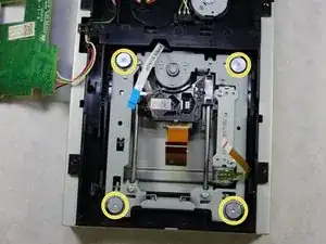
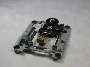
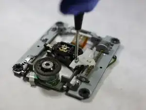
Locate the 4 circular hex screws that secure the laser rail assembly.
-
Using your T6 hex screw driver remove these 4 screws.
-
-
-
Flip the laser rail assembly over to expose the screws.
-
Remove the screw connecting the laser lens to the plastic fastener.
-
-
-
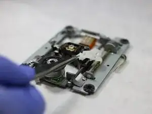
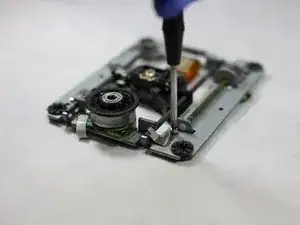
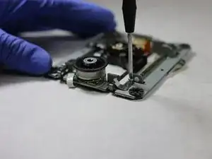
Remove the screw connecting the metal fastener to the rail.
-
Remove the metal fastener that holds the rod to the rail after removing the screw.
-
-
-
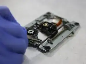
Push the rail end to the side and out from under the metal latch.
-
Slide the lens off the rail. Set aside the rail assembly.
-
-
-
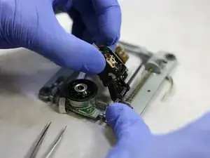
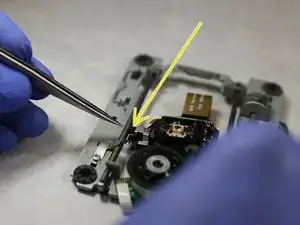
Using the spudger, release the plastic clamp holding the ribbon to the laser lens.
-
Using your fingers gently pull the ribbon out of the plastic clamp.
-
-
-
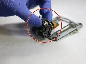
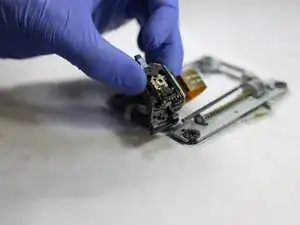
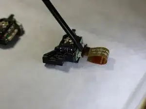
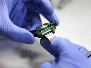
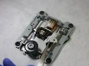
This is the lens
-
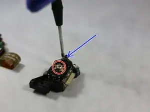
Remove the screw holding the metal fastener to the old lense.
-
Remove the now unsecured metal fastener.
-
-
-
Connect the ribbon to the replacement lens by sliding it in place then closing the plastic fastener.
-
Place the removed metal fastener on the new laser lens and use the removed screw to secure the fastener to the replacement lens.
-
-
-
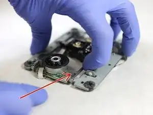
Slide the replacement lens onto the right rail
-
Make sure to clip the other side of the lens onto the left rail
-
-
-
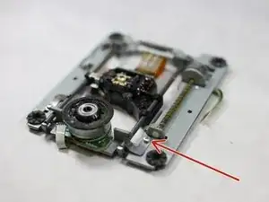
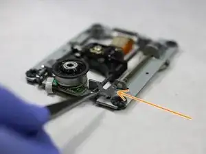
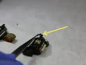
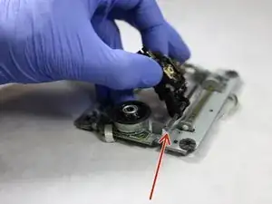
Slide the unsecured right rail back under the metal latch. (metal latch is pointed to by the arrow)
-
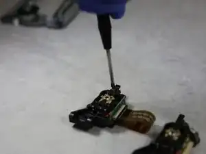
Place the metal fastener removed from the rail previously back in position and secure it with the screw that was removed.
-
-
-
Retrieve the plastic fastener and the accompanying screw.
-
Reattach the plastic fastener to the laser lens and use your philips head screw driver to re-secure the screw. The lens should now be attached to the rail.
-
-
-
Position the rail assembly within the disk drive
-
Use the 4 previously removed screws to secure the position.
-
-
-
Place the motherboard back in position.
-
Use the plastic pins to resecure the motherboard back to the disk drive.
-
-
-
Reattach the 3 ribbon wires to the motherboard.
-
These are the 3 wires that were detached in steps 5 & 6
-
Reattach the screw removed from the motherboard in step 7. This is the only screw that'll completely secure the motherboard to the disk drive.
-
-
-
Replace the cover remove the cover
-
Flip the disk drive over and reattach the four screws removed from the cover in step 4.
-
-
-
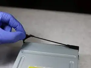
Flip the disk drive and reattach the elastic band.
-
You are done with replacing the laser lens.
-
Nice Job!
-


If you followed all the steps you should have a working XBOX 360 S.
One comment
Thanks, took me around 30 min to do this. Everything is written in detail. I like that.
You first have to detach the foam on the front in order to take the cover off because the foam is gluing the two halves together. Just slide a spudger underneath it along the bottom and sides, making sure you're actually going underneath it and not tearing it.
Annaliese P -