Introduction

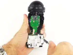
The LED light on the MiP indicates what mode the robot is in. If this light is malfunctioning, using the MiP is difficult.

  1. iUngOsHkGDJuNdcg
    iUngOsHkGDJuNdcg
    mbPtI1McjuEwTSM2
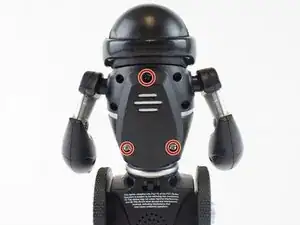
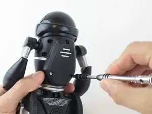
    • Remove the three 12.0 mm Phillips # 2 screws from the battery cover.

  2. NqkVBAHBS5kZHQNf
    NqkVBAHBS5kZHQNf
    GaoNIPBQABdnSmVg
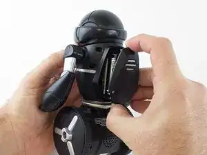
    • Carefully pull the battery pack from the robot.

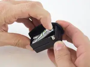
    • Remove the batteries from the battery pack.

  3. ShHZaoFaVfGIcOpE
    ShHZaoFaVfGIcOpE
    gRck2QqL1BgcAgaL
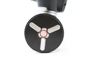
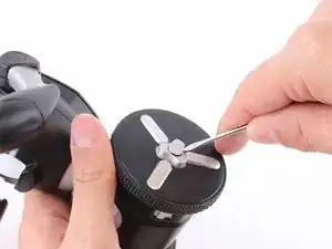
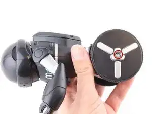
    • Use a metal spudger to carefully pry off the hubcap without marring the plastic wheel or hubcap.

    • This plastic material is not replaceable. Any damage will be noticeable.

    The hubcap won't come out. It's flat & tight. Even a tiny screwdriver for eyeglass repair can not get under it. Any tricks forgetting it out?

    donna.hester7 -

  4. Vw1biTfGQB2ytDTy
    Vw1biTfGQB2ytDTy
    sYNdOfABTm1aOeEL
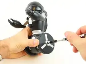
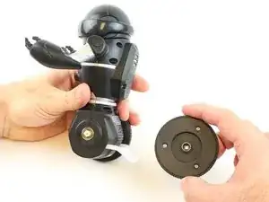
    • Remove the 12.0 mm Phillips #2 screw.

    • Hold the wheel in place, or it will rotate as you attempt to remove the screw.

  5. LjtN3AW5hM5dY5xG
    • Pull the wheel off of the square axle.

    • Do not use excessive force while removing the wheel. Pulling too hard on the wheel can damage the axle.

  6. QRE1AV5hMaBMVaSW
    QRE1AV5hMaBMVaSW
    DgPR3wiOABFgfO62
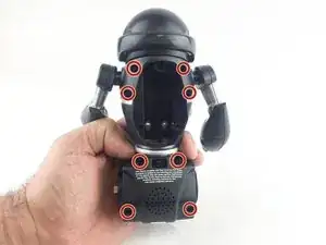
    • Remove the eight 9.3 mm Phillips #1 screws from the back of the robot.

  7. MXIY2QcErJJkWeJa
    MXIY2QcErJJkWeJa
    rExo3TPTffKKS2I4
    wj21NxCUX42JNiP2
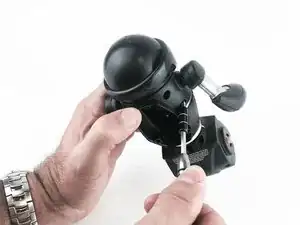
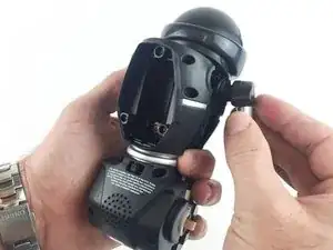
    • Remove the arms from the body.

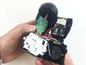
    • Carefully open the body compartment.

    • Open the compartment slowly. There are wires connecting the two body pieces together. If pulled too hard, the wires and/or the motherboard could be damaged.

  8. 4HBDLMgoWCHrQC1t
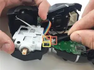
    • Using precision tweezers, disconnect the following three bundles of wires:

    • Connecting the battery pack to the motherboard.

    • Connecting the power switch to the motherboard.

    • Connecting the speaker to the motherboard.

  9. UxBJPHuQwHfRRMNB
    UxBJPHuQwHfRRMNB
    WwuKhInVeIldQxU2
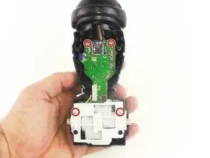
    • Remove the four 7.5mm Phillips #1 screws.

  10. 2fIu142PqF36kmKS
    2fIu142PqF36kmKS
    XfdLkutSBh12R1uo
    • Carefully pull the motor and motherboard assembly straight out from the base.

    • Be careful not to break the plastic rods that go through the motor assembly and are connect to the shell.

  11. VATXSeINaSnHaByY
    • Use the precision tweezers to unplug the bundle of wires.

  12. o3q256GOEYsfqwrv
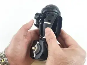
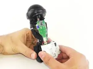
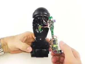
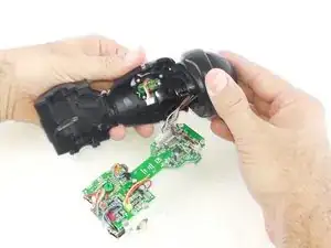
    • Slide the head back to separate it from the body.

    • The motherboard does not need to be separated from the head to replace the LED light.

  13. D2OcKRBCJaQxXNEu
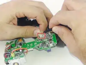
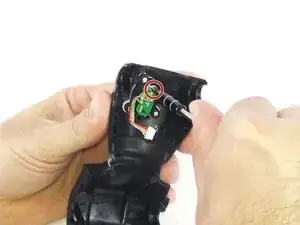
    • Remove the 7.5mm Phillips #1 screw.

    • The LED light is soldered to the small circuit board.

Conclusion

To reassemble your device, follow these instructions in reverse order.
Courtney

Member since: 04/02/16

236 Reputation

0 comments