Introduction

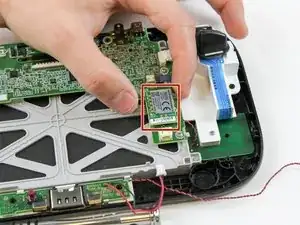
This guide will help you to replace your camera. For this replacement, you will need to use tweezers.

  1. dKTaxZjIUAsyAXlI
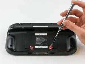
    • Place Gamepad face down and remove the two 4.7 mm screws with a Phillips size #00 screwdriver.

    tried to unscrew the 10 Tri-Wing size Y1 screw with my iFixIt toolkit

    unfortunately the tool is too “fat” and short, it cannot reach 4 screws on the corners of the gamepad.

    having the iFixIt toolkit and needing to purchase an additional slim screwdriver it’s a shame…

    Antonello Iannone -

  2. jQnDZvXRQvPOXfpG
    • Lift and remove the battery plate.

  3. qZN3PgyACtZ5Tw4i
    qZN3PgyACtZ5Tw4i
    nDakTZouVNlkKPKx
    o4RQ44lFuusIk4uU
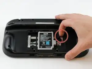
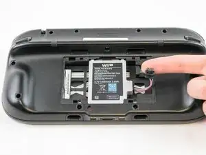
    • With your finger, press down and pull back on the battery connector plug.

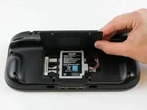
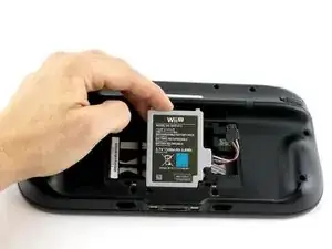
    • Remove the battery from the battery case.

    Battery lifts up from the bottom not the top like the photo shows.

    Tyler Schommer -

  4. IlOVIxDuCaqAuWCO
    IlOVIxDuCaqAuWCO
    iNj1oAZjk4bbQA1g
    CfComIPOOBMDkYhT
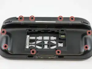
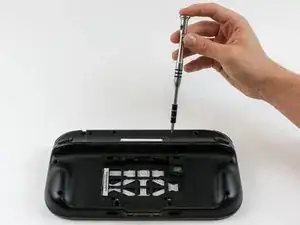
    • Remove 10 9mm screws with Tri-Wing size Y1 screwdriver around the outer case.

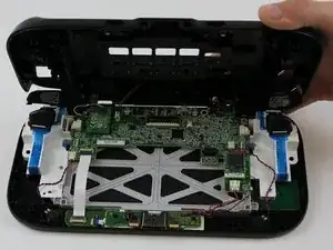
    • Lift up on the back of case.

    • Lift gently because the rumble motor in the back of the case is still connected by a cable to the motherboard.

    I used a small blade tip to life up on the black squares that covered the screw holes. Replacing them after.. I skipped that as it seemed impossible they would even stick back down.

    Chris -

    I am having trouble getting the two screws on the hand grips as the screws are too deep. What should I use to get them?

    [deleted] -

    I ended up having to buy some cheap amazon screwdrivers and are very disappointed

    [deleted] -

  5. MBTkFeprlTH425NV
    • Unplug outer case rumble motor connector from the motherboard with your fingers.

    Do not pull by the wires! If you do, you better be pretty good at soldering.

    Brandon -

    I agree. A circle over the plug would have been better as the picture looks like you just pull on the wires lol.

    Chris -

    Thanks for the comment. I did get a set of tweezers and the negative cable broke anyway. They really could have done a better job at using a different connector for that.

    Kristen Bartholomew -

    Great. Didn't pull on cord. Whole thing ripped off.

    August -

    Why in the world is this thing so tightly connected?

    Andrew Moore -

    Thanks for the comment. I did get a set of tweezers to try to pull it out but still ended up breaking the negative cable. They really could have used a better set of cables and connectors for this.

    Kristen Bartholomew -

  6. lQpCMiEjbuhZ6I1t
    lQpCMiEjbuhZ6I1t
    FVXXJNUkL6InP1Lb
    • With your fingers, unplug the left speaker cable from the motherboard.

    Speakers are connected with solder so removing them is not possible without requiring soldering later on. I left them both connected and instead of removing the motherboard completely I just "hinged" it carefully down to facilitate the work following step 18.

    dietcokediva -

    Thank you for offering this info because I spent 20 minutes between scratching my head and searching for any alternatives to just the image above, which had a wire nut/housing (and mine certainly did not). As I began to have an anxiety attack (

    Missy Leap-Courtney -

    Mine also did not have connectors for the speaker. But like mentioned above, I was able to do repair WITHOUT the need to unsolder the speaker wires. Thanks!

    Louis Bellanca -

  7. ToqplyUlLtDhitp1
    ToqplyUlLtDhitp1
    nvgg1TfBOOiNpeoE
    • Remove the right speaker cable that's connected to the motherboard with the tweezers.

    Note that on some units (presumably later ones), the speakers are soldered onto the motherboard.

    Ryan Finnie -

  8. TUsHKGephHImxTpX
    TUsHKGephHImxTpX
    xDCTCAKa4Np4ILLa
    1Mh3m4Cirwhv3Kci
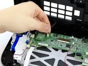
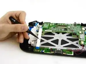
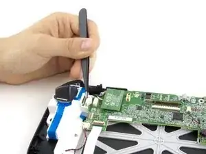
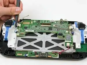
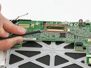
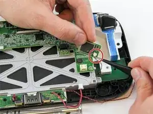
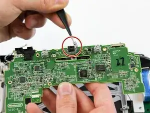
    • Open the top and bottom clasp that connects the white flex cable to the motherboard with the tweezer.

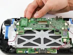
    • Remove the white flex cable with the tweezers.

    Attention! You have to flip up gently the small plastic cap on top of the ribbon connector. Do not try to slide the plastic cap horizontally. This method holds for all ribbon connectors.

    Marc Peetermans -

    Why is it necessary? The white flex cable doesn’t seem to block the way to the Bluetooth unit.

    metm98 -

    It is a easy step and makes dealing with everything else a little easier.

    Chris -

    Isn’t it WiFi?

    Brayton Dickey -

    This step is unnecessary, there is no reason to go through it.

    jonv85 -

    Why would you do this? It’s not blocking anything. Not even near the wifi module.

    N64 -

    I’m just curious, as a technician gamer, you say it makes it easier, but I don’t see how it would affect the Bluetooth, sure the motherboard or the touch screen, but the Bluetooth chip is out of the way. I’m not trying to be critical, just want to understand.

    Hydron -

    Pointless step for this task.

    MrW -

  9. VFYrKgHvDyR2hwNI
    VFYrKgHvDyR2hwNI
    kdgLFbkFoWwUTXvU
    • With your fingers, lift and remove WiFi board.

    • Remove the board carefully as there are still two wires attached.

    These little boards (Bluetooth and NFC) have a small connector but also have double sided tape holding them down. So you may need to apply more force than expected to remove these due to the tape.

    Louis Bellanca -

    Isn’t it Wi-Fi?

    Brayton Dickey -

  10. GrAwqAXQSAOJBcbA
    GrAwqAXQSAOJBcbA
    5Ao4YuCIoJpQbkkC
    • Disconnect the black and white wires off of the back of the WiFi module.

    One important thing to note here is how the black and white wires are routed to the board. You should take a picture since if you do not route these the same way, the wires can interfere with the button or get trapped when you assemble the case back possible blocking a screw hole.

    Louis Bellanca -

    Isn’t it Wi-Fi?

    Brayton Dickey -

    Any idea what the name of the white wire is? I accidentally broke through mine.. having trouble finding a replacement

    Winder Mere -

    how do i route the bluetooth anntenas

    Zach -

  11. OtZh1PSCUSQo3NL3
    • Lift and remove the WiFi module.

    Isn’t it Wi-Fi?

    Brayton Dickey -

    Does it really matter?

    martin8777 -

    Thanks a lot for the guide. I just fixed my gamepad and it appears to be working good. Just one question: why do you include the step in which you remove the flatflex cable to the other pcb? It seems unnecesary

    Carlo Zanardi -

    Do you happen to know where you can find replacement wires for the back and white wires?

    Amber S -

  12. MtipRhFwfaa6veQB
    • Disconnect the analog connector with tweezers.

    The connector on the right side is also on the left side.

    Paulus 68 -

    There was a little tab on the top of the male end of the connectors that I had to push to get them out.

    Reed Deemer -

    Take a small flat head screw driver and push out and to the left on top of the white part of the connector. If you try to use tweezers on this model it will not come out.

    Steven Vallarian -

  13. QRhZGrF16LT4yXFC
    QRhZGrF16LT4yXFC
    CD6qqS56kOePKoCP
    • Remove the blue connector using tweezers.

    Looks like there are 2 of these connectors - left and right side

    Louis Bellanca -

    Lift the little gray tab before you pull the blue ribbon out.

    theonlygeezy -

  14. XPE2Qd4OoYphLJVr
    XPE2Qd4OoYphLJVr
    eD1jQZOnNNLoDADx
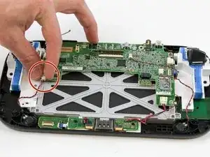
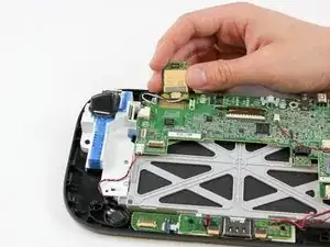
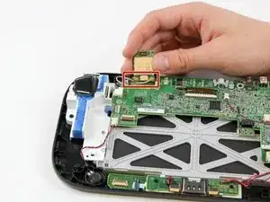
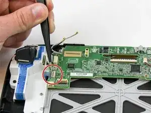
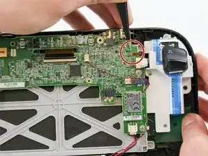
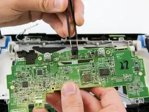
    • Carefully lift the black clasp. It is prone to breaking if only lifted from one point. Remove the brown ribbon by using the tweezers.

    • Unclasp and release the small digitizer ribbon cable to the left of the brown ribbon. Be careful, the clasp breaks easily.

    There is also a small connecter on the left side from the big connector.

    Paulus 68 -

    The small connector is the digitizer (touch senor panel) - The large connector is the actual display

    Louis Bellanca -

    For the small connector, lift up the black part on top from this side.

    theonlygeezy -

    I broke that small connector (the lid) how can I fix that? The flex is still goes there but I won't get touch response unless I apply some pressure to it!

    davisrayler -

    if you fixed it, can you tell me how did you do it?

    Bast -

    The small grey ribbon has a clasp holding it down. It needs to be opened in the opposite direction of the black clasp on the wide ribbon before you disconnect the ribbon.

    Ginny Buhler -

  15. qQTGcCU3bhhYfXxq
    • Remove the small orange ribbon with the tweezers.

    These tiny connectors are difficult to see how to manipulate. Similar to other ribbon connectors, there is a lever that flips up to release the ribbon cable. However, unlike the larger connectors, the lever flips up from the opposite side that the connector enters. Run your tweezers up the back side of the connector body, and the grey top should flip to vertical. Then the ribbon cable will slide out.

    Matt Cross -

    This small connector is attached to the screen as well.

    Louis Bellanca -

    What do I do if I broke off the gray top cover that went over the wire things.

    Amber Umphrey -

    You probably don’t need this anymore, but that happened to me a while ago and now i’m gonna have to buy a new motherboard. Your motherboard is as good as done for

    The Boi -

    Snapped it off too. Tried hot glue.with no luck. Does anyone know if Motherboard s are interchangeable? I have Version B

    Foe Suar -

  16. gE5HgSkLUC4wZ2Wx
    gE5HgSkLUC4wZ2Wx
    xRdgQKRUcBOLCvUN
    dqTupMcdcCCTnqR1
    • Remove these two connectors to the motherboard with your fingers.

  17. xijb6MlRQNphbEO1
    xijb6MlRQNphbEO1
    qDwHYWPjeKVdUNfT
    • Remove the NFC communicator.

    • When removing the NFC communicator, be careful with the small connector on the back side.

    • Remove the small connector plug-in on the back.

    When trying to remove the red and black cords, it came off the green board. Is there a way to reconnect them?

    Judy Swenson -

    I didn't disconnect the cable, isn't really necessary.

    Paulus 68 -

  18. GMo6kaTU3PJUMUcv
    GMo6kaTU3PJUMUcv
    hNCP4Ee6j1eVdIaU
    f2FljBbnKVGlJSAI
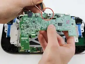
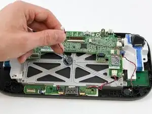
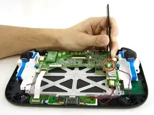
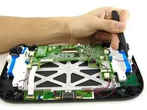
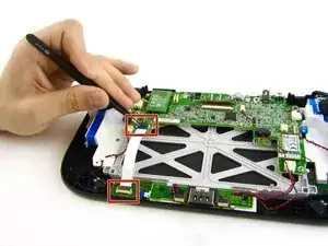
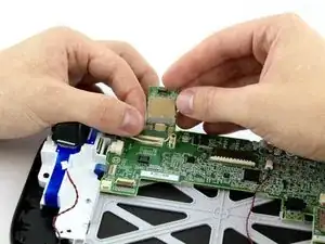
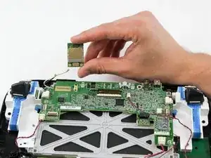
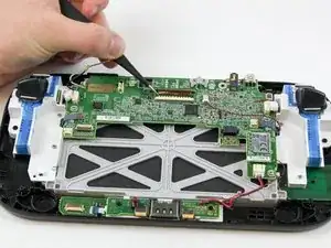
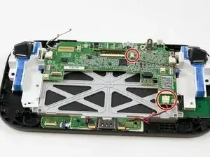
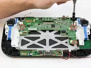
    • Remove the remaining three 5.1 mm screws using the Phillips size #0 screwdriver.

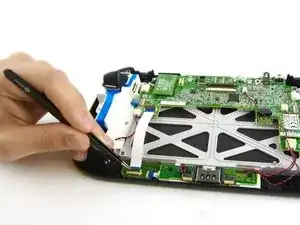
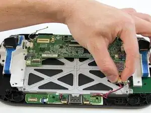
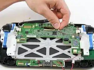
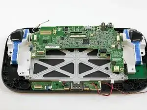
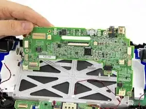
    • Lift and remove the mother board.

    There's a 4th 5.1mm screw along the bottom edge in the middle.

    Bobby Elrod -

    The speakers were soldered as mentioned above, so I carefully folded the motherboard down to facilitate work

    dietcokediva -

  19. 2q4oaR3DjaFIgIYS
    2q4oaR3DjaFIgIYS
    LBUDx5ZcZ2JoYDQV
    • Flip motherboard over.

    • Remove the metal housing around the camera with tweezers.

  20. MfpwZ165NdGZLOBS
    • Pull the camera out using the tweezers.

Conclusion

To reassemble your device, follow these instructions in reverse order.

Valentina Cerruty

Member since: 10/02/16

3345 Reputation

0 comments