Introduction

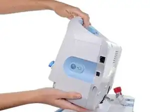
Use this guide to Remove or replace the rear housing of your Welch Allyn 6000 series Connex vital signs monitor.

PLEASE NOTE: This repair guide was developed by the iFixit team based on Welch Allyn's own service manual. Neither iFixit nor this repair guide is endorsed by or affiliated with Welch Allyn.

  1. TjvKGcZHTTRpKIHd
    TjvKGcZHTTRpKIHd
    5SI4bnN1HQ1KYE4m
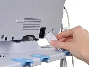
    • Unplug the AC power connection cable.

    You do not need to do all these steps.

    With dry hands and a firm grip, just press on the arrow with all fingers and slide battery door out.

    Anthony S -

  2. bbDJnVKmbVV4BViU
    bbDJnVKmbVV4BViU
    JhgMAUjTgSf4GfhO
    VBSAMaaGvx2EElGY
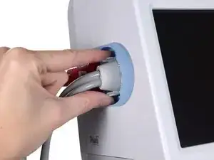
    • Place your thumb and forefinger on the blood pressure (NIBP) hose connector. Squeeze the side tabs until the connector releases.

    • Always grasp the hose by the connector. Do not pull on the hose itself.

    • Pull the connector away from the connector port.

  3. 2iCwfQGtNSG4wQRt
    2iCwfQGtNSG4wQRt
    L6vXC5yRSGG3GsCo
    OnRNoitXBdNus6tQ
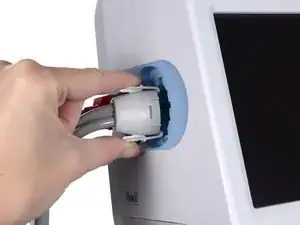
    • Place your thumb and forefinger on the Pulse oximetry (SpO2 or combined SpO2/SpHb) cable connector. Squeeze the side tabs until the connector releases.

    • Always grasp the cable by the connector. Do not pull on the cable itself.

    • Pull the connector away from the connector port.

  4. TbkVHKJORxGtctDf
    TbkVHKJORxGtctDf
    QTnjfkoduNAhrmJv
    • Grasp the temperature probe and pull it up to remove it from the monitor.

  5. dTILOBYQAMgbZLNK
    dTILOBYQAMgbZLNK
    GuCT6pQIHQg6od64
    tJYRRMPKjAKI1UIQ
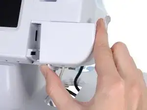
    • Remove the cover of the temperature module by pressing the tab and sliding the cover to the right.

  6. Ol2RVWWR4XTDRePW
    Ol2RVWWR4XTDRePW
    3ZZTXnoDZyJ24XUl
    ZrUNfbhExJLwgGST
    • Depress the spring tab on the temperature probe cable connector and withdraw it from the probe port.

  7. HcIeL1uMGhXPFZiZ
    • Remove the flathead screw on the USB networking door.

    • Loosen the captive Phillips #2 screw securing the monitor to the stand.

  8. h21Bv5plwdcBMZ3K
    • Holding the monitor securely, open the USB networking door.

    • You may have to lift the monitor slightly to allow the door to swing out from the stand mount.

  9. 6EKwOYvIhS5giFFl
    6EKwOYvIhS5giFFl
    LhmaXdSTomkCnMlm
    • Detach any accessory USB cables from USB ports on the monitor.

  10. 3qhU2WSXpITZOXDZ
    3qhU2WSXpITZOXDZ
    cehiN24Gs1eUGG53
    PPXiDx5LtTeP3BL2
    • Slide the monitor off of the stand tray.

  11. RCj21m2QFjFskJVZ
    RCj21m2QFjFskJVZ
    vdOtWPG1yfCOddOI
    bNtENQaH2EUJJ1RY
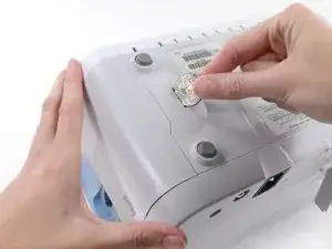
    • Place the monitor upside down on a clean surface.

    • Insert a coin into the slot and push to open.

    • Choose a coin that fits comfortably into the slot.

    • Remove the battery cover.

  12. 2pIwNsNENrbADWhl
    2pIwNsNENrbADWhl
    pQPGJj3lJiJZLwQY
    vfOFZ6MXuPpdP1uZ
    • Use the plastic label to remove the battery from its recess.

  13. jnXewmK6A5uBMByX
    jnXewmK6A5uBMByX
    muOtIRWRUrnCTjaQ
    • Open the communications door to access the lower left-hand rear housing screw.

    • Remove the four Phillips #2 screws (labeled 14 in the service manual) from the rear housing.

  14. FE1A2AhWvkCcO1rP
    FE1A2AhWvkCcO1rP
    GYetBLXgBcqJEpWG
    • With the handle/alert bar facing you, begin to lift the rear housing from the left side, holding the right side securely.

    • Do not attempt to separate the rear housing from the monitor, it is still attached with several cables.

  15. YGGFpijsqFCV1Qao
    • Support the rear housing while you disconnect the cables in the following steps.

  16. vnURghFHSf5ndxjy
    vnURghFHSf5ndxjy
    Y3xVtueRyRYTPSaM
    1rGG1sICu2XZrQWV
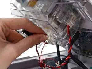
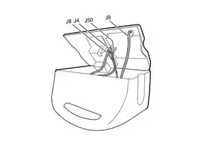
    • Disconnect the fan cable (labeled connector A in the service manual) from its socket in the power supply.

  17. SkAChMELZbefHhAj
    SkAChMELZbefHhAj
    EGKZmDlgOUU3yTFA
    nN1oECJMqWwnm2SM
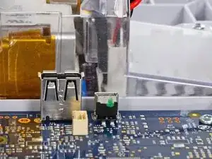
    • Unplug the small USB connector from its socket (labeled J4 in the service manual).

  18. BtT1So2nkAinhuwL
    BtT1So2nkAinhuwL
    VCttpBIcWoINmFgd
    nXqHeFXPbIHZKYfY
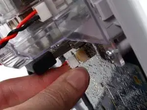
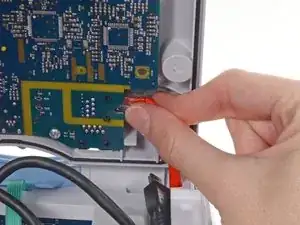
    • Disconnect the communications power cable from its socket (labeled J50 in the service manual).

    • Only pull on the connector itself and not the socket. This connection is very tight, work the connector slowly and gently.

  19. vQTry3KCoyTcE16L
    vQTry3KCoyTcE16L
    tucDLV6uiBO6sSUV
    QXFUGCeSSRmUtTiA
    • Unplug the large USB connector from its socket (labeled J8 in the service manual).

  20. Qfq2rPClfuGXx6Lt
    Qfq2rPClfuGXx6Lt
    TnOwVumxn1JWCRK1
    Hb3qyKuno2IY1e4f
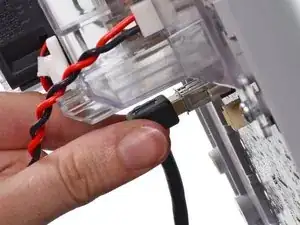
    • Press the tab on the ethernet cable and unplug it from its socket (labeled J9 in the service manual).

  21. fWswX5IbWIAiyMyK
    • The following connector requires two hands to disconnect. Flip the rear case over, and lay it on its back to gain access to the power supply cable.

  22. xodWUYEi2gocY33H
    xodWUYEi2gocY33H
    4vAXJ3lQ5SJCPHtH
    QUmWkLYjTuVXaIX2
    • The power supply cable is secured by an interlocking connector that must be held open to unplug the connector.

    • Insert the flat end of a spudger down into the power supply cover between the socket clip and the power supply connector.

  23. FAOl61cCRwWW2ehB
    FAOl61cCRwWW2ehB
    p6jOWCQbTYbTUreg
    GJsVXDU6sqGSCRFA
    • Grasp the power supply cable firmly and lift both it and the spudger from the channel in the power supply housing to unplug the connector.

Conclusion

To reassemble your device, follow these instructions in reverse order.

Sam Goldheart

Member since: 19/10/12

465329 Reputation

0 comments