Introduction

Use this guide to remove or replace the bellows on a Wacker BS50-4AS REV 101 (2019) Vibrator/Rammer.

This model requires up to 0.7 liters of SAE 10W-40 oil to replace drained oil.

  1. MLifHqlYxerSwXNl
    MLifHqlYxerSwXNl
    ipgNkCbKH1uGuLIO
    • Ensure the device is powered down and cool to the touch before starting your repair.

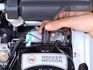
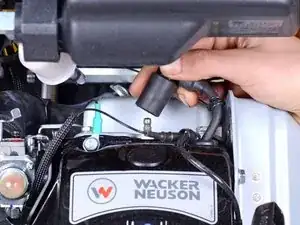
    • Firmly grip the base of the spark plug wire's connector and pull it away from the spark plug to disconnect it.

  2. gOcTOgwCYcgNLARX
    • Use a 1-1/16 inch socket to break loose the oil sight gauge near the bottom of the device.

    • Do not fully remove the oil sight gauge yet with the device in this upright position.

    • The oil sight gauge doubles as the oil drain and fill plug.

  3. WOcJDYG3ZNU1UeuV
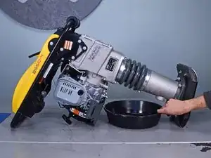
    • Lay the device down horizontally with the oil sight gauge facing down.

    • Position a shallow oil drain pan underneath the sight gauge.

  4. GkUmvjnGRiKiHSPy
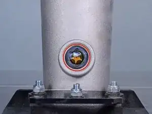
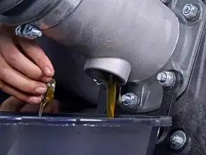
    • Remove the oil sight gauge.

    • Let the oil drain until drips are infrequent.

    • Replace and retighten the oil sight gauge.

    • This model requires 0.7 liters of SAE 10W-40 oil.

  5. sBLtBfNhU3JIHtMX
    sBLtBfNhU3JIHtMX
    OPCUyUVWTgcKJWDb
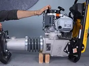
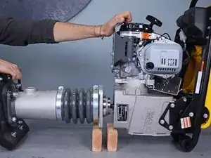
    • Flip the device onto the work surface such that the motor and handles face up.

    • Place two separate blocks of wood underneath the seam between the leg assembly and crankcase.

    • Once the two halves separate, each side will need to be supported.

  6. QahNJt34QUdEFEoq
    QahNJt34QUdEFEoq
    SZOVqjcjQUDdOON2
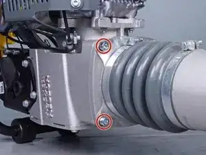
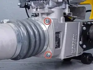
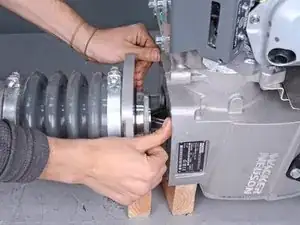
    • Use an 8 mm hex key socket to remove the four bolts securing the leg's guiding cylinder to the crankcase.

    • You may need to use an impact driver or breaker bar to break these bolts loose.

    • During reassembly, ensure each bolt has its accompanying lock washer.

  7. cWYx4EptleW3FJ2A
    cWYx4EptleW3FJ2A
    WDsrkEpDKryQugpN
    • Pull the leg assembly away from the rest of the device.

    • Ensure each half stays adequately supported.

  8. lFU6ojegjZGXJVyN
    lFU6ojegjZGXJVyN
    ceYMi6vdiMvQO4i3
    yLXPW4UqcG6IgU1N
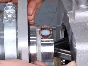
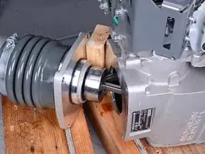
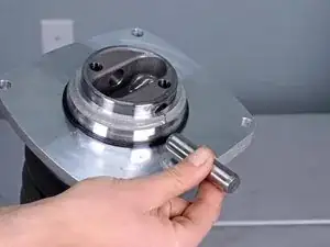
    • Continue to separate the two halves by compressing the bellows until the nylon plug covering the piston pin is visible.

  9. kl6vqGBXSPv1gyAx
    kl6vqGBXSPv1gyAx
    KJ2VsAU1kyGBSZyd
    • Tip: To compress the bellows, insert a block of wood between the two halves and pivot the leg assembly off of the crankcase to compress the guide cylinder, revealing the pin.

  10. 1WEO5sFB6nKCByEt
    1WEO5sFB6nKCByEt
    oeX1ZFKp6LH1E2FS
    mMxRMSpLW5wDxsIo
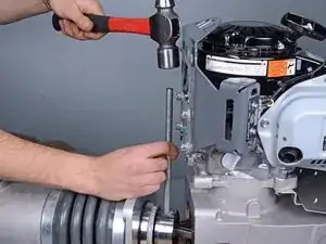
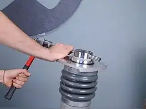
    • Use an appropriately-sized punch and a ball-peen hammer to tap the pin out of its hole on the guide piston until it is no longer securing the connecting rod.

    • Once the piston and connecting rod are separated, the two halves become completely disconnected and will need to be adequately supported.

    • During reassembly, ensure that both nylon plugs are reinstalled and are flush with the surface of the guide piston.

  11. 6lQwbolJ5KTIwFht
    6lQwbolJ5KTIwFht
    oByAJJ6SWgFNfOTb
    • Remove the leg assembly from the crankcase.

  12. 5G6sqYQQwxpjyQw4
    5G6sqYQQwxpjyQw4
    IrHvirlxHaFfdmE6
    • Use a punch and hammer to tap the pin out of the guide piston.

    • Once the pin is removed, the guide cylinder may spring up due to the compression of the bellows.

    • During reassembly, the bellows will need to be compressed to uncover the pin hole on the guide piston.

  13. s11K1LMQ3vl4Zkbt
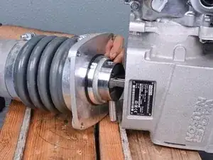
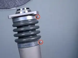
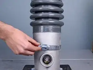
    • Use a 13 mm socket or large flathead screwdriver to loosen the two hose clamp bolts securing the bellows to the leg assembly.

  14. aiGnQQ13ZwCiGOSf
    aiGnQQ13ZwCiGOSf
    RkKVEUChyRlxY1ox
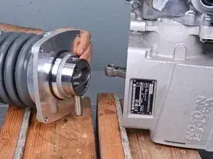
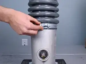
    • Lower the bottom hose clamp away from the bellows and let it rest at the base of the leg assembly.

  15. C4sB2h63eYplbHuJ
    C4sB2h63eYplbHuJ
    LRYOAp3OEIiZKppt
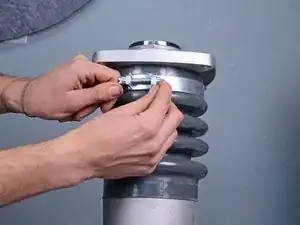
    • Open the top hose clamp and pull it down, past the bellows, and let it rest at the base of the leg assembly.

  16. tOesESCZQWKsxcFJ
    tOesESCZQWKsxcFJ
    yDYHqRXoUqnZIh5B
    bwvgnwpOTjkiIgRQ
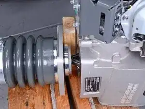
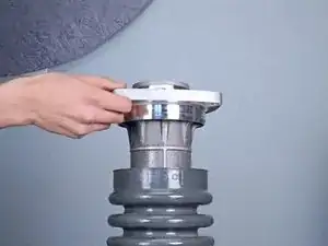
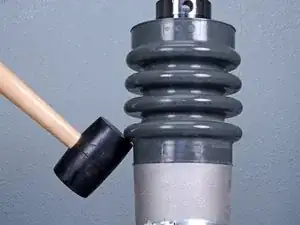
    • Use a rubber mallet to tap the bellows down and off of the top of the guide cylinder.

    • Tap around the entire circumference of the bellows, pulling one edge down at a time.

    • During reassembly, use the rubber mallet to tap the bellows into place onto the lip on the cylinder.

    • Once loose, pull the bellows off of the lip on the guide cylinder.

  17. raCPMEKXUsYJYblI
    raCPMEKXUsYJYblI
    4pkBZW1hVC1leLtm
    eqrSEFP6HCRFhwCc
    • Lift up and remove the guide cylinder.

  18. ThWQeMfBXLTRywFU
    ThWQeMfBXLTRywFU
    5dEP55tYaEBLMGM3
    6mybQtOHngFQ2FyT
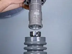
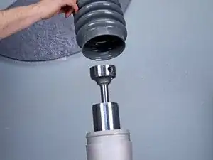
    • Use a rubber mallet to tap the bellows up and off of the top of the protective pipe.

    • Tap around the entire circumference of the bellows, pulling one edge up at a time.

    • During reassembly, use the rubber mallet to tap the bellows into place onto the lip on the pipe.

    • Once loose, pull the bellows off of the lip on the protective pipe.

    • Remove the bellows.

Conclusion

To reassemble your device, follow these instructions in reverse order.

After reassembly, tilt the device upright and check the oil level through the sight glass. The oil should cover 1/2 to 3/4 of the sight glass to be considered full. This model requires up to 0.7 liters of SAE 10W-40 oil.

Carsten Frauenheim

Member since: 10/03/20

110978 Reputation

0 comments