Introduction
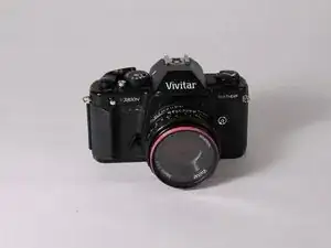
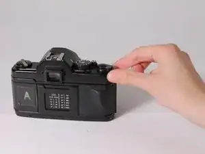
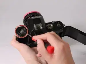
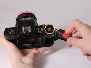
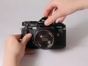
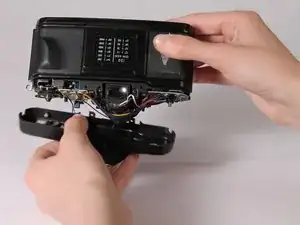
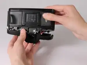
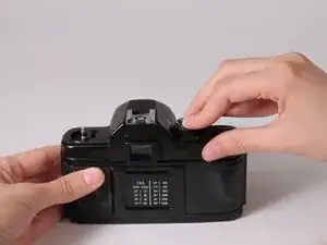
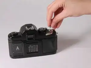
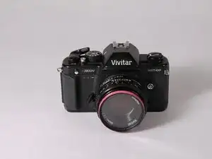
Over time the frame counter in the camera will become loose. When this happens the user will not be able to tell what frame they are on when taking photographs. This leads to wasting film or ripping the film off the canister. This guide will show how to adhere a loose frame counter so the user can go back to shooting photographs.
Tools
-
-
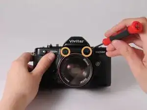
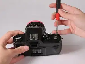
Unscrew the front screws on the camera with a Philips screwdriver.
-
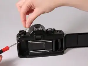
Unscrew the back screws on the camera with a Philips screwdriver.
-
-
-
Remove the film advance lever by unscrewing the bottom screw with a Philips screwdriver.
-
Remove the plastic cover to uncover the metal lever.
-
-
-
Remove the screw holding the metal component of the lever with a flathead screwdriver.
-
Once the screw has been taken off, remove the metal lever.
-
-
-
Set the speed dial to Bulb mode and the ISO to the lowest setting before taking it off. This makes sure you are at the correct settings when it is placed back together.
-
Carefully put a flathead screwdriver into a notch in the middle of the dial on the center piece and turn it counter-clockwise.
-
Once loosened, remove the speed dial with your hands.
-
-
-
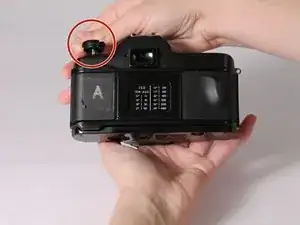
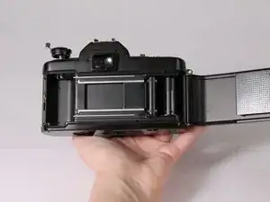
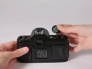
Open the camera back by pulling up on the film rewind crank.
-
Once open, push the rewind crank back down and insert a screwdriver into the notch.
-
With one hand holding the screwdriver in the notch, wind the crank counter-clockwise to remove it.
-
-
-
With a flathead screwdriver, twist the metal washer counter-clockwise to remove it.
-
Remove the washer underneath the advance lever in the same way.
-
-
-
Remove the loose frame counter.
-
Apply a small amount of glue to the area and wait approximately 5 minutes for it to dry.
-
Put the frame counter back into place, lining up "26" to the indicated notch.
-
-
-
Place the shutter release button pieces into the indicated spot. The larger piece goes in first, then the smaller piece fits into that one.
-
Put the view finder back into place by sliding it in as shown.
-
-
-
Screw in two screws on the back of the camera.
-
Screw in the other two screws on the front of the camera.
-
-
-
Reassemble the 5 pieces of the shutter speed dial.
-
Place the spring into the dial.
-
Place the lens load indicator on top of the spring.
-
-
-
Place the top of the speed dial onto the lens load indicator.
-
Place the gold piece into the indicated area.
-
-
-
Keeping the spring compressed, carefully place the dial on top of the camera that matches the settings you set during step 4.
-
Tighten the dial by placing a flathead screwdriver into the notch and turning clockwise.
-
-
-
Place the correct washer back underneath the rewind crank and tighten with a flathead screwdriver.
-
Open the back of the camera and place the screwdriver into the notch.
-
With one hand holding the screwdriver, place the rewind crank onto the peg and turn clockwise until tight.
-
-
-
Place the washer on the spot underneath the advance lever and tighten with a flathead screwdriver.
-
Place the advance lever on top of the washer and screw it into place using the flathead screwdriver until tight.
-
-
-
Place the plastic cover onto the advance lever and use a Philips screwdriver to place it together.
-
You're done! Go take some great photos!
