Introduction
Tools
Parts
-
-
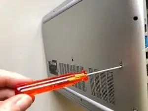
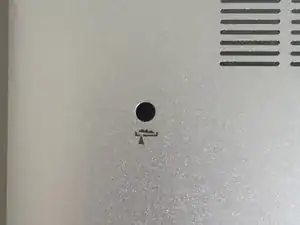
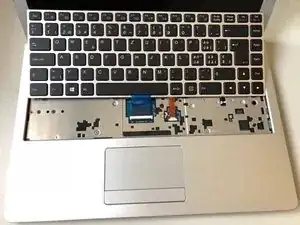
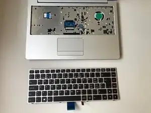
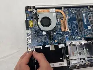
Using the hole provided under the case (see picture), push the keyboard out using a thin screwdriver or some other solid object.
-
Hold onto the keyboard as you push the keyboard so as not to damage the two cables still attached.
-
-
-
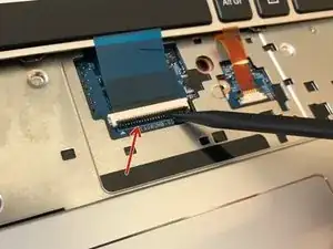
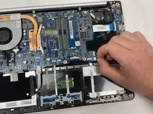
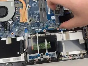
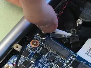
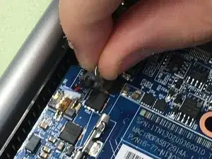
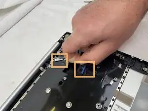
(Blue Cable) Push up on the thin black portion on the connector and gently pull out the blue ribbon cable until it comes out.
-
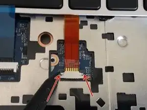
(Orange Cable) Remove the orange cable by sliding the gray part of the connector towards the screen, then gently pull on the ribbon cable.
-
-
-
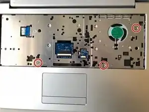
Unscrew the three screws that were under the keyboard. Be sure to hold onto these.
-
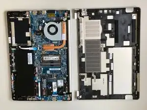
After these are removed, you can now remove the lower part of the case from the rest of the computer.
-
-
-
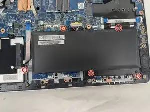
Remove the five Phillips screws securing the battery.
-
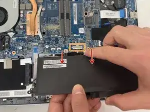
Unplug the power connector and lift the battery out in the direction of the arrows to remove it.
-
-
-
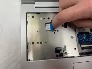
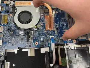
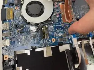
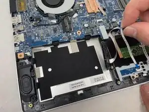
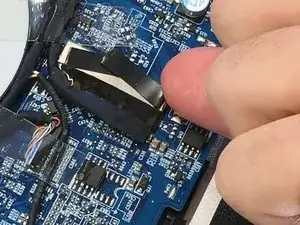
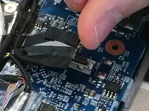
Lift the retaining latch and unplug the ZIF cable found under the keyboard.
-
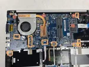
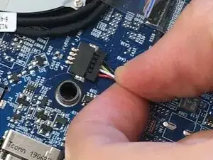
Disconnect the nine marked cables as detailed in the following steps.
-
Remove the four screws securing the motherboard to the case.
-
-
-
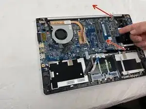
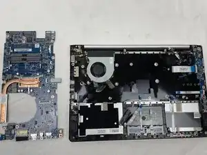
Once the screws have been removed, carefully lift the motherboard from the end indicated by the arrows.
-
-
-
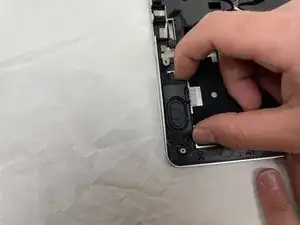
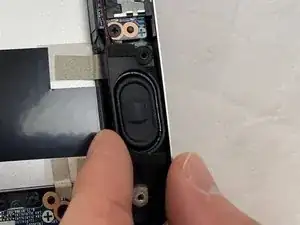
Remove the right speaker.
-
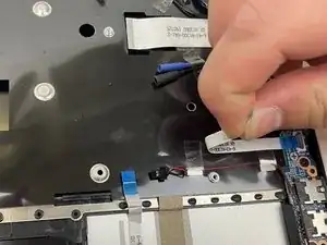
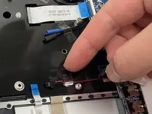
To remove the left speaker, first peel off the microphone/headset cable, then the adhesive strips.
-
-
-
Remove the left speaker.
-
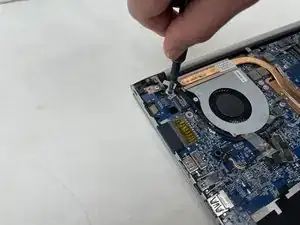
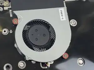
Remove the two Phillips screws securing the CPU fan to the case and remove the fan.
-
Remove the two screws securing the audio connector board.
-
-
-
Lift the audio board at the point indicated by the red arrow and slide it away from the chassis in the direction of the orange arrow.
-
Remove the Phillips screw securing the power connector board.
-
Lift out the USB connector board in the direction indicated by the arrows.
-
-
-
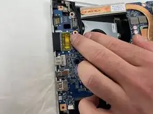
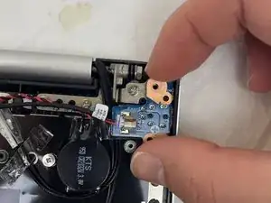
Unplug the DC input board, remove the single Phillips screw securing it and remove it.
-
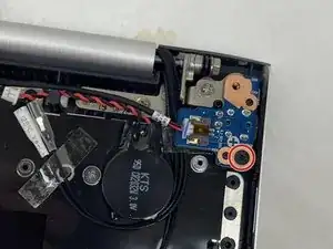
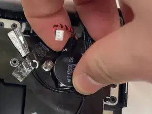
The CMOS battery is secured to the case with adhesive. Simply peel it off to remove it.
-
-
-
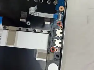
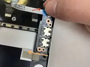
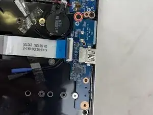
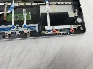
Remove the two screws holding the LED board on the chassis and remove it along with the ribbon cable.
-
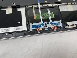
Remove the two screws securing the touchpad button plate.
-
-
-
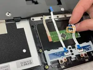
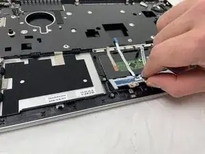
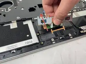
Lift the ZIF connector retaining tab and unplug the button cable on the right.
-
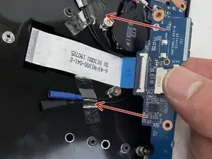
Grasp the LED board between the two cables.
-
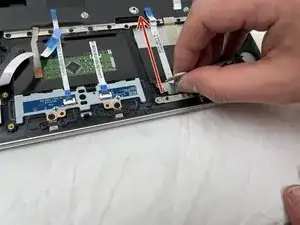
Following the direction of the red arrow, peel the two cables from the case.
-
-
-
Peel off the pieces of tape holding the cables onto the chassis.
-
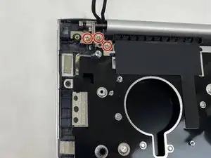
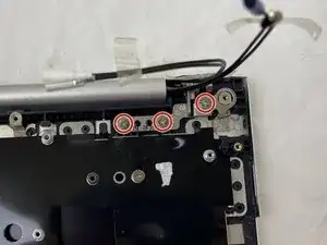
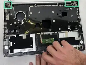
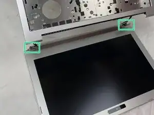
Remove the six Phillips screws securing the hinges, three on each side.
-
-
-
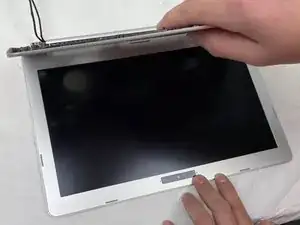
While holding down the display, lift the chassis up to about a 45 degree angle.
-
The case will slide out once there is sufficient clearance.
-
To reassemble your device, follow these instructions in reverse order.
