Introduction
This is a prerequisite-only guide! This guide is part of another procedure and is not meant to be used alone.
-
-
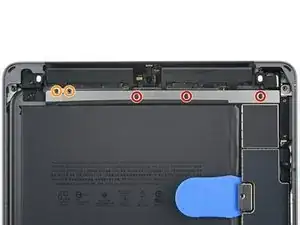
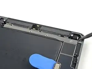
Use a Phillips #00 screwdriver to remove the five screws securing the the upper component bracket:
-
Three 1.4 mm-long screws
-
Two 1.9 mm-long screws
-
-
-
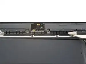
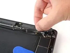
Use the pointed end of a spudger to lift up the upper component bracket until you can grip it with your fingers.
-
-
-
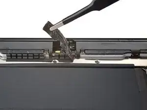
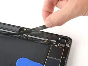
Use your fingers to peel the upper component bracket away from the tape.
-
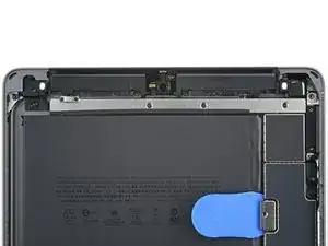
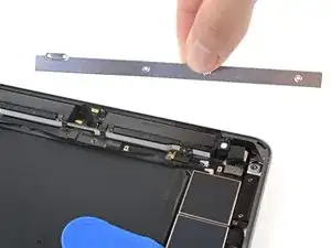
Remove the upper component bracket.
-

Conclusion
To reassemble your device, follow these instructions in reverse order.