Introduction
Tools
Parts
-
-
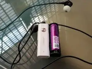
No more 2-3x downtime a day and dropped calls with this great receiver! With battery upgrade, you'll be looking at an enormous 23-26 hours of non-stop music listening enjoyment!
-
-
-
Most, if not all of these kind of devices are powered by 1s LiPo battery, with 3.7v nominal voltage.So the safest replacement would be power source outputting 3.5-4.2V range. ~25mA power draw requirements is estimated from the original battery life.
-
I've chosen 14500 LiIon (LiMn flavor for more safety) for the upgrade. 3x AAA would also be an option if NiMH is your thing, but make sure not to use the internal charging mechanism if you choose the latter option!
-
Do caution as misusing or mishandling the battery may cause a FIRE or EXPLOSION which may result in personal injury or property damage. The user must have an appropriate understanding of the potential dangers of LITHIUM ION BATTERIES.
-
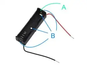
A 14500 or AA battery holder will work for this, but some modifications may be needed as described in the following points:
-
(A) Add a blob of solder here, this will ensure it works with flat top 14500 batteries.
-
(B) Cover the top, bottom, and holes with epoxy glue, for more piece of safety.
-
-
-
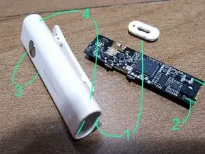
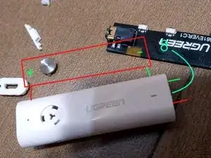
Now on to the main part. The first step would be to remove the board from the case, and prepare the modifications to attach the battery holder onto the case.
-
(1) This might be the trickiest part of the upgrade. The Ugreen case cover can be found on the bottom of the device, neatly glued. Carefully separate the cover sides with a paper cutter, then use a small minus screwdriver to pry off the cover. As you can see, I failed to preserve the beauty of it, but you might have better luck!
-
(2) Now carefully pull the board on its sides with a plier. Wiggle it a bit, as the case had a small board holder slot on the other end.
-
(3) Remove the power and volume buttons, by pushing the pins from the inside. I found it impossible to put back the board in later with these two parts on!
-
(4) Drill couple of holes with a small hand drill or soldering iron. These holes will be the opening for the battery holder wires.
-
-
-
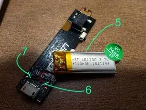
Now here's the board and the puny 110mAh LiPo battery. Get rid of it!
-
(5) Remove the battery from the board, by carefully prying the double tape sticking the battery to the board.
-
(6) Cut the positive wire.
-
(7) Cut the negative wire.
-
You may want to prepare the solder joints at this point, cleaning up the remaining of the original battery cables.
-
-
-
I did not took any photos during this process, so instead, I've made some drawings to show how the holder was prepared during soldering of the wires on the board.
-
Prepare the surfaces to epoxy, by scratching them with a paper cutter and wiping it clean. This will ensure that the epoxy glue sticks well enough to the surface.
-
Put on the wires as described in the picture, leaving 1-2cm exposed on the bottom of the case. Prepare the wire ends for soldering, by pretinning it.
-
(8) Now insert the board back into the case, but do not fully insert it yet. Also bear in mind that solder points should face down, the reverse of what is shown in the picture.
-
Solder the battery holder wires, and finally, fully insert the board back into the case.
-
Put the cover back on. I needed a tiny piece of double tape to firmly hold the edges to the case, but your mileage may vary.
-
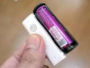
Finally, glue to battery holder to the case with epoxy.
-
-
-
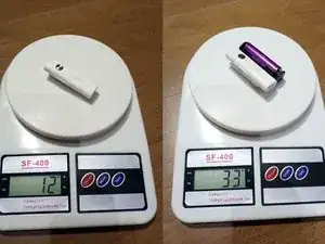
Wonder what kind of weight we're looking at now? While the battery does make the receiver much heavier than it was, but it still is a pleasure to clip on the shirt! And of course, nothing beats the enjoyment of 23 hours battery life given by the 650mAh 14500!
-
But always remember, watch the volume when listening to IEMs!
-
I wonder if I should do the same thing to my BTR1K in the mail!
-
To reassemble your device, follow these instructions in reverse order.
One comment
What the csr ic code?
