Introduction

  1. QH6QTCiBPHChluI1
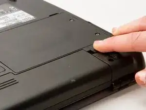
    • Make sure that the laptop is off and unplugged.

    • Turn the laptop over.

    • Slide back the left lock, and you should hear a click when it is successfully locked back in.

  2. fKOkrOaMdbaPR4bK
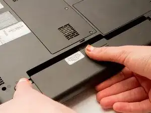
    • Rotate the laptop 180 degrees so that the battery is near you.

    • Hold back the spring slide and pull the battery out.

  3. iZECH3TAuFq4Nsuf
    iZECH3TAuFq4Nsuf
    kJZUuBJDJ3qwmlAm
    mEWCjohuEJluFhfa
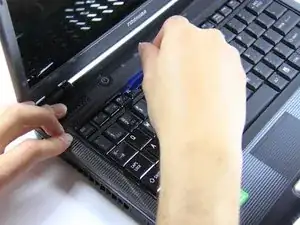
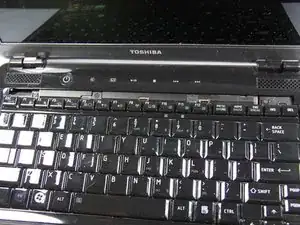
    • Situate the laptop so that it is open and the display is facing you.

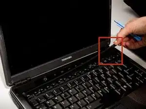
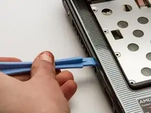
    • Use the plastic opening tool to pry the black plastic insert upward. The insert can be found at the top of the keyboard.

    • Once the insert is loose, carefully remove it from the device.

  4. VAcgmoskJsLGTXnX
    VAcgmoskJsLGTXnX
    vHdpxCeKJMSTovnC
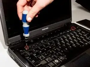
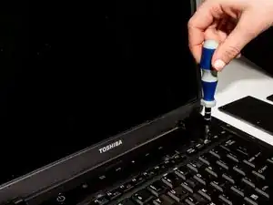
    • Using #1 Phillips Screwdriver, remove both of the 5 mm screws that are located beneath the insert.

  5. fjaNYDsgqpEcMpJr
    fjaNYDsgqpEcMpJr
    16NXVDQBAdt3DUiK
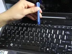
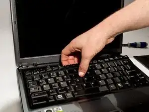
    • Use the plastic opening tool to begin removing the keys off of the device.

    • Once the keys are off, gently remove the keyboard. Be careful of the ribbon cable that still connects the keyboard to motherboard.

  6. WcEfMBRthSBXdLan
    WcEfMBRthSBXdLan
    l55OWdy4jpBZN4Hf
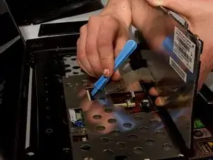
    • Lift up the gate on the ZIF socket to release the ribbon.

    • Ease the ribbon connecting the keyboard to the motherboard out of the ZIF socket.

  7. FELeTyhLwuAhHuhH
    FELeTyhLwuAhHuhH
    aRHX3HvHCAkyRVZ4
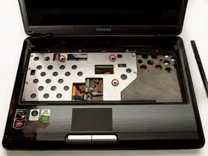
    • With the keyboard removed, locate the marked screws.

    • Remove the marked, 5mm screws using the #1 Phillips Screwdriver.

  8. ReRJMgW4Rjlctx2A
    ReRJMgW4Rjlctx2A
    Z3ISX3npSdQbS14t
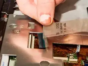
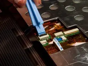
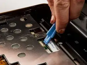
    • In the opening above the mouse pad, use the plastic opening tool to push up the black gate of the ZIF socket.

    • Remove the ribbon from the ZIF socket.

  9. oR3kjcuWZpIKQhfT
    oR3kjcuWZpIKQhfT
    2XlrPTjNA4MRgYDB
    n1N56wXXHWugHJcT
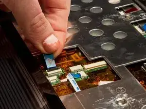
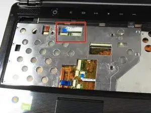
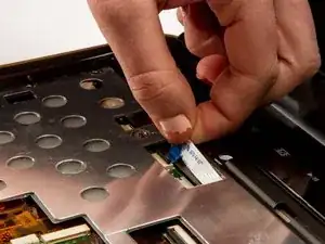
    • Locate the wide opening at the top near the screen.

    • Use the plastic opening tool to open the black ZIF socket.

    • Remove the blue ribbon.

  10. APmHO5ODmlxekTKF
    APmHO5ODmlxekTKF
    e2taypXPxgHhOlfd
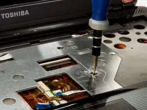
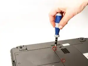
    • After removing the screw in step 3, carefully close the laptop and put it face down. Locate the center panel.

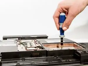
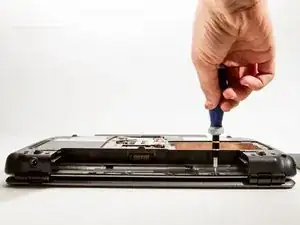
    • Remove the three, 3 mm screws using the #1 Phillips Screwdriver.

  11. dfLCEkf4gWNOXKvW
    dfLCEkf4gWNOXKvW
    5ZwgNHH6fNou5NK6
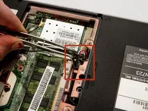
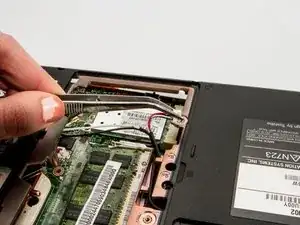
    • Grasp the power cable with your tweezers and remove it from the wireless antenna.

  12. N1Uy3UixEeVvpxYD
    N1Uy3UixEeVvpxYD
    BkJVJd2YTRR3bRPo
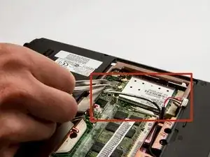
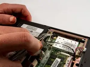
    • Locate and remove both the white and black antenna leads with the tweezers.

  13. hodlvVICqAE1JMpR
    hodlvVICqAE1JMpR
    CQTamQGWHJbcKFLs
    h4dnODoENybmUG4i
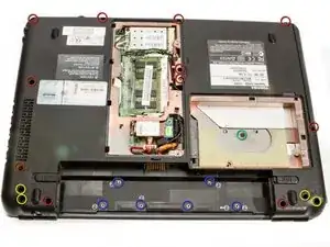
    • Remove screws for back assembly.

    • 11 x F5 (5 mm #1 Phillips)

    • 6 x F2 (2 mm #0 Phillips)

    • 4 x F8 (8 mm #1 Phillips)

    • 1 x F3 (3 mm #1 Phillips

  14. v4JRQ4lNWFlZfKXR
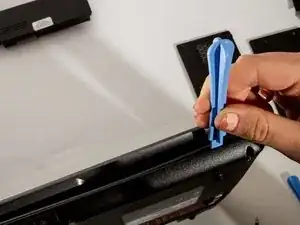
    • Use the plastic opening tool to release the back panel from the laptop.

    • If all of the screws are removed it should come off with very little effort. Do not force it. If it still feels attached, check that you didn't miss a screw or two.

  15. CtRcbXdKql1I6rR5
    CtRcbXdKql1I6rR5
    XoVqnkGnj5XZqwb4
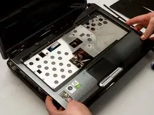
    • Use the plastic opening tool to separate the top faceplate.

    • The faceplate is the plastic surface and the metal piece under the keyboard.

    • Carefully lift the faceplate off of the base by sliding the plastic opening tool around the outside of the device. You'll hear clicks as you do this.

    • Prying apart the faceplate will be a little hard, but try not to bend it too much - you do not want to crack it.

  16. lNDIjHgZPoEl1ZRL
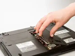
    • Lift the back panel and carefully disconnect the main power cable.

  17. APd56dbNFNJJVhMs
    APd56dbNFNJJVhMs
    A2WZNArxVrWK1tfg
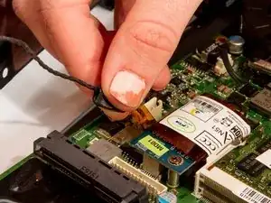
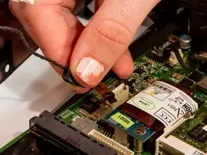
    • Remove the black signal cable attached at the blue circuit board.

  18. B25VnX5TVn4ZXt5a
    B25VnX5TVn4ZXt5a
    mgL3aOIR1KbKPrd2
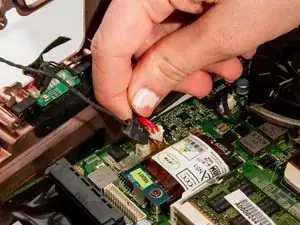
    • Remove auxiliary power cable attached to the blue board at the back of the laptop.

  19. krJEIOqQmoIxPwep
    krJEIOqQmoIxPwep
    YVODshoLUQZMo5sb
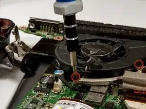
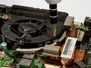
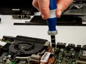
    • Remove the fan mounting screws with a #1 Phillips Screwdriver.

  20. ngExdZuGlL1ersrB
    ngExdZuGlL1ersrB
    sSZbpJyCDKxEgX6X
    sYpB6Q1bc2XNsJEr
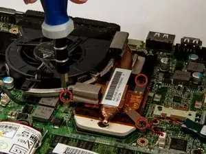
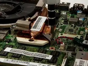
    • Locate and remove the heat sink mounting screws using a #1 Phillips Screwdriver.

    • These screws will be tight as they hold a critical component onto the processor. You may need to use a little extra elbow grease to remove them.

  21. KdRoLSDla3nyjmpq
    KdRoLSDla3nyjmpq
    1qUlTjSIxZ6CvnYo
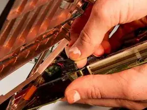
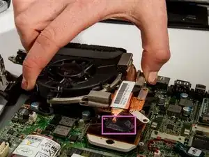
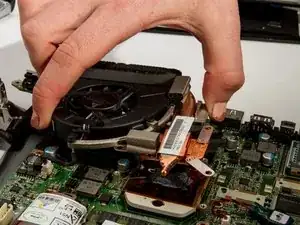
    • Carefully lift the fan and heat sink assembly.

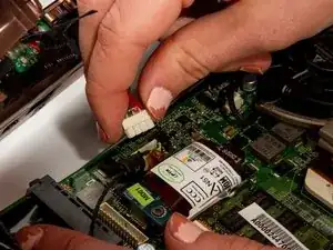
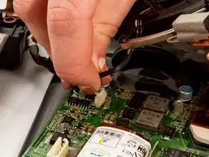
    • Detach the fan power cable from the motherboard with your fingers by squeezing the white plastic connector and wiggling gently from side to side.

    • There will be a grey goop between the copper heat piping and the back of the processor, (indicated in pink). This is thermal paste and allows heat to flow properly.

    • Be sure to replace any missing thermal paste when installing the new fan.

Conclusion

To reassemble your device, follow these instructions in reverse order.
Brandon Kirklen

Member since: 11/01/13

311 Reputation

0 comments