Introduction

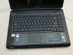
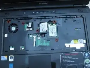
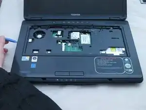
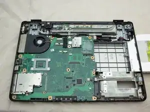
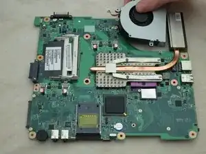
Use this guide to replace the cooling fan in your Toshiba Satellite L305-S5946 if you notice your current part is not functioning properly, which may be indicated by the computer shutting down unexpectedly.

  1. OFyVSJM22YeKOGbR
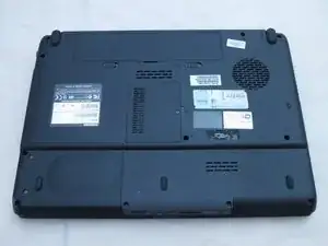
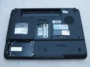
    • Place the laptop upside-down with the display hinges facing away from you.

  2. EsonHCyJ5QuFkVCr
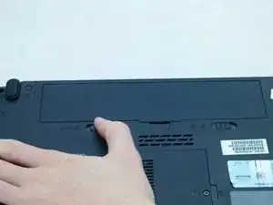
    • Slide the latch for the left battery bay to the left.

  3. ZCoKtRD4nnq3KVgK
    ZCoKtRD4nnq3KVgK
    TLjMRGGGuhacnD3A
    UIAHElAWljgtQM2Y
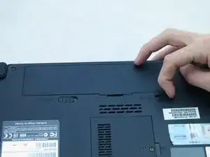
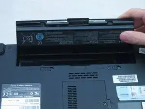
    • Slide the latch for the right battery bay to the right and hold.

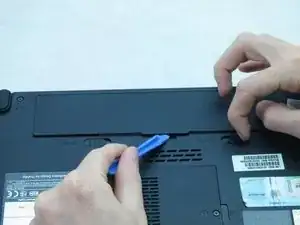
    • Continue to hold the latch while using a plastic opening tool to lift and remove the battery bay cover.

    • Remove the battery.

  4. wSoK52GKdUeROQTp
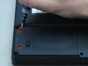
    • Loosen the two captive screws on the bottom left corner of the hard drive using a Phillips #1 screwdriver until you hear a click.

  5. CSINWcTJ3XCdxOGe
    CSINWcTJ3XCdxOGe
    rPhV5r5gmhCrka3A
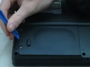
    • Lift the hard drive cover using a non-marring iFixit opening tool.

    • This will expose the hard drive.

  6. MIombvRf3kOWCIra
    MIombvRf3kOWCIra
    SLJPmTbTyxflKPn1
    rOCoOQwDWxpMRjNR
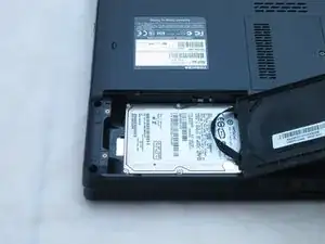
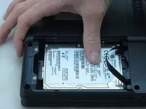
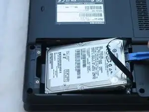
    • Slide the hard drive to the left using your fingers.

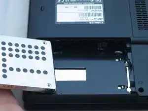
    • Remove the hard drive by inserting an iFixit opening tool under the right side of the hard drive and carefully lifting it out.

  7. lrJh6NFtlEgElCqg
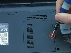
    • Using a Phillips #1 screwdriver, turn the screw on the RAM cover until you hear a click.

    • This is a captive panel screw and remains with the cover.

  8. ijWRPLn56olfGygf
    ijWRPLn56olfGygf
    MBiG5yvdH1hPLJfv
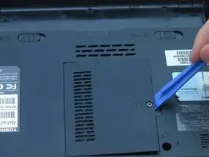
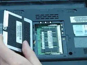
    • Remove the RAM cover by inserting the plastic opening tool into the indent and lifting.

  9. vnTsEhKEylSDyY3V
    vnTsEhKEylSDyY3V
    MFjkdyCLCAqGNSMY
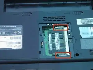
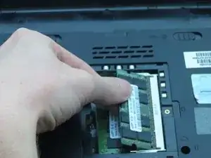
    • Push the white and silver retaining clips away from each side of the RAM card using your fingernails.

    • The RAM card should pop up at an angle.

  10. mVcSjSPdTDjVkAA4
    mVcSjSPdTDjVkAA4
    BfsYVLnytwfRlHdA
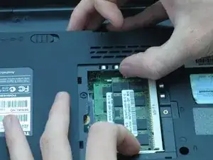
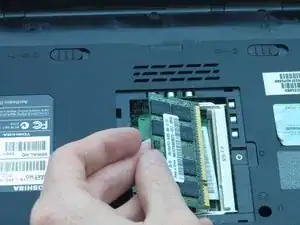
    • Pull the RAM card away from the computer.

    • Repeat Steps 6 and 7 to remove the other RAM card that may be installed.

  11. WDNTVhXFdba1Q5tg
    • Place the laptop right-side-up so the screen faces you.

  12. ya2ToiUZWBwqeIR3
    ya2ToiUZWBwqeIR3
    omSQvSVTfnCkfd6I
    LoUhZjgPh5nUmDAM
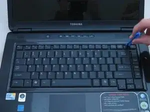
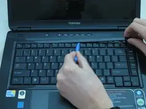
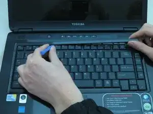
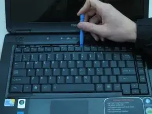
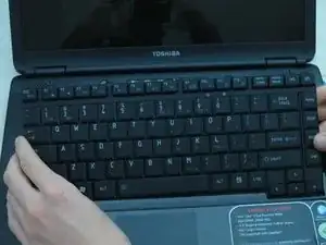
    • Remove the strip of plastic at the right furthermost edge of the keyboard using a plastic opening tool.

    • Insert the plastic opening tool at either end of the strip.

    • Lift upwards and proceed to the other end while repeating this lifting process every one to two inches.

  13. 4MDtijhvwGjSUa4G
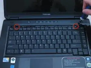
    • CAUTION: do not allow hardware or debris into the CPU fan and duct.

    • Remove the two 3-mm screws at the top edge of the keyboard using a Phillips #00 screwdriver.

    • These are not captive panel screws and, once loosened, will be free to move about the assembly.

  14. SrZoJ4wbxBGDcDIf
    SrZoJ4wbxBGDcDIf
    mGnJdWURItcMDNoH
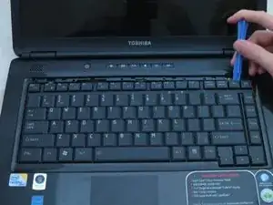
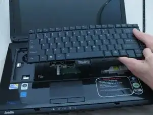
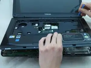
    • Pry the top of the keyboard loose from its casing using a plastic opening tool.

  15. doWVXbehiZFqFIMq
    • Gently grasp the top of the keyboard and pull it up and toward the screen.

    • CAUTION: Pulling too hard could damage the black ribbon cable under the keyboard.

  16. ZsFTBTJRNKfqmD6I
    ZsFTBTJRNKfqmD6I
    1UBTIk1LVHXd1KOF
    2XRclGECBmKuKqkR
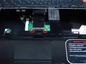
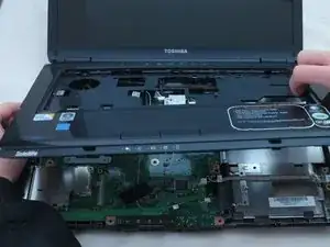
    • Gently push the two tabs locking the black ribbon cable.

    • To remove the black ribbon cable from the motherboard, slide the keyboard toward the screen.

    • You may now safely separate the keyboard from the laptop.

  17. RVJUZV5NXBJlOodR
    • Place the laptop upside-down with the display hinges facing away from you.

  18. mbZaRHEVLMvUMUYj
    • For the following steps, use a Phillips #1 screwdriver.

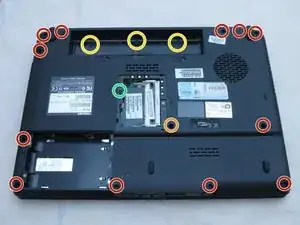
    • Remove the twelve 6-mm screws that border the bottom of the laptop.

    • Remove the 6-mm screw located in the lower middle of the device.

    • Remove the three 3-mm screws located in the battery bay.

    • Remove the one 4-mm screw located near the RAM.

  19. fRV4TWbU1G3pSkpf
    • Place the laptop right-side-up so the screen faces you.

  20. 1Iq1ElTIqYxIeY43
    • CAUTION: do not allow hardware or debris into the CPU fan and duct.

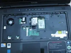
    • Use a Phillips #1 screwdriver to remove the five 6-mm screws in the keyboard slot.

    • These are not captive panel screws and, once loosened, will be free to move about the assembly.

  21. RaqjqdySYwXH31KF
    RaqjqdySYwXH31KF
    dKXsbNeokJLSWGyn
    pMDgYKxc5HhXwHqu
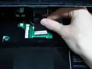
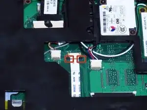
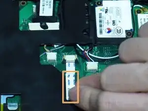
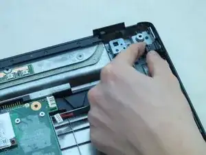
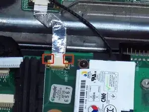
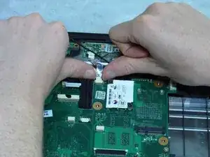
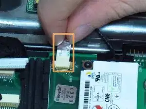
    • Lock the white ribbon cable into place by gently pulling on the two black tabs.

    • Remove the white ribbon cable by pulling it towards you.

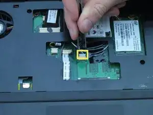
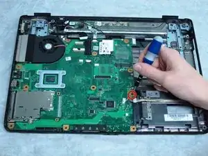
    • Remove the connector that has the blue, red, black, and white wires using tweezers.

  22. oPi5sL2HevjfolfU
    oPi5sL2HevjfolfU
    psHndWE5YK1aAE1p
    CO3rbyjOHWXVkTZD
    • Separate the laptop upper casing from the lower casing by using an opening tool around the sides of the case to pry it apart.

  23. kBUYNNfIMRwsT5HH
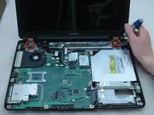
    • Remove the four 6-mm screws from the two hinge pads using a Phillips #1 screwdriver.

  24. DUrNqnZgIZGHnlvg
    DUrNqnZgIZGHnlvg
    aHlFGm4oEIiHSFEL
    MCR3o5PGFFTMHtDO
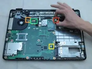
    • For the following steps, use tweezers:

    • Remove the connector equipped with the black and white wire.

    • Remove the connector equipped with the black, green, red, yellow, and white wires.

    • Using your fingers, remove the large connector located at the top right corner of the motherboard, as shown.

  25. QeZTFKvsmFslvlBA
    QeZTFKvsmFslvlBA
    CJkye3qjPQCT1MiI
    • CAUTION: do not allow hardware or debris into the CPU fan and duct.

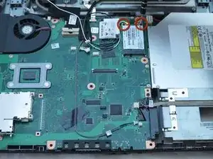
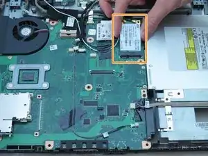
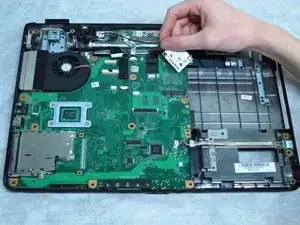
    • Remove the two 3-mm screws from the card equipped with black and white wires by using a Phillips #00 or Phillips #1 screwdriver.

    • These are not captive panel screws and once loosened will be free to move about the assembly.

    • Gently remove the card with your fingers.

  26. AMwcfgH5NoyEBxtG
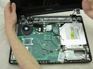
    • Remove the display assembly and put it aside.

  27. LhIZYTStlYSn26Dv
    LhIZYTStlYSn26Dv
    mQWOpYCumygrMEkx
    VwGQC1fhWeVyPXrH
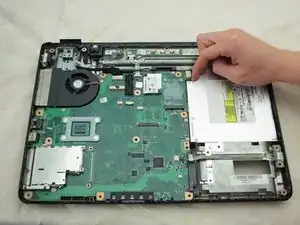
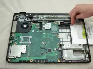
    • Slide the DVD out of the opening on the right using your fingers.

  28. GQVZpSGCKtGnhkup
    GQVZpSGCKtGnhkup
    yisEaPYubBJRCqZR
    2LJOviuBC1YuGyWx
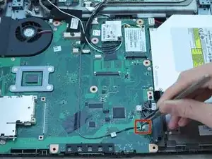
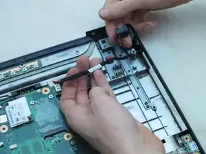
    • Remove the power jack connector.

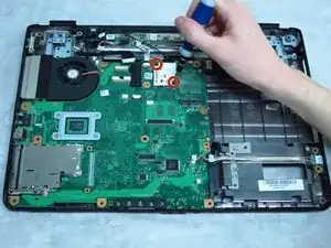
    • Remove the connector equipped with one red wire and one black wire.

    • This connector may be hidden beneath a cooling fan wire.

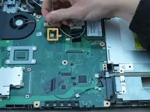
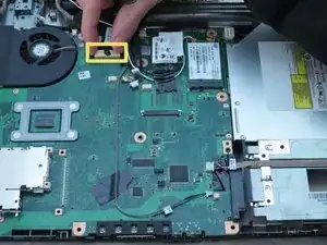
    • Remove the connector equipped with red, yellow, green, white, and black wires.

    • Remove the large connector near the fan.

    • Remove the power jack cable and socket from its housing by pulling gently.

  29. fO44vOHiwWu4HfJp
    fO44vOHiwWu4HfJp
    OgcpPpWVShb2LZLk
    kLfYVb43hhMZmiMh
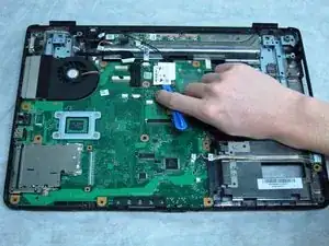
    • Gently push the two black tabs until they stop moving.

    • Remove the silver ribbon cable from the connectors by pulling gently.

  30. GrLWBsIOHRSik4aX
    • CAUTION: do not allow hardware or debris into the CPU fan and duct.

    • Rremove the 6-mm screw near the hard drive using a Phillips #1 screwdriver.

    • This is not a captive screw and, once loosened, will be free to move about the assembly.

    don't forget the screw by the hardbrive.

    Bob Brown -

    How do you reconnect the cooling fan cable to the motherboard. The little white connection head does not want to slide in. I have been trying for hours. Very frustrating.

    tinadberg -

  31. XFGTGk1ituYPjmCv
    XFGTGk1ituYPjmCv
    LfbNVZPKMVB3duME
    r3MkfmLGLDoAGNjI
    • Remove the two 3-mm screws from the card connected to the black wire using a Phillips #00 screwdriver.

    • These are not captive screws and, once loosened, will be free to move about the assembly.

  32. Hb6V1nFPDJKBeXbX
    Hb6V1nFPDJKBeXbX
    RWVrTBHGh6tK4axG
    YnXqKAY5udYHHCFS
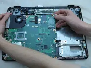
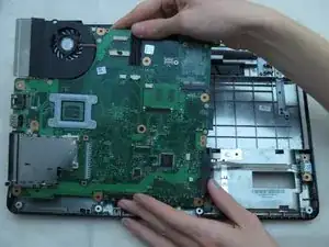
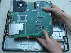
    • Gently lift the top right side of the motherboard. Pull it upwards to the right and away from you.

  33. axtcpoIOBcMaZpr5
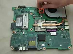
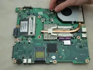
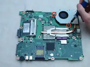
    • Flip the motherboard over. Remove the two 3-mm screws from the fan using a Phillips #1 screwdriver.

  34. qqkZixxmMUGiY3sa
    qqkZixxmMUGiY3sa
    aFFgjLjIapvKgUay
    • Remove the housing equipped with red, blue, and yellow wires using your fingers.

  35. XaWbBngAOmDWaYnW
    • Remove the fan from the heatsink using your fingers.

Conclusion

To reassemble your device, follow these instructions in reverse order.
Michael Erberich

Member since: 18/04/13

130 Reputation

0 comments