Introduction
If you are experiencing problems when trying to use headphones with the Toshiba Satellite C55-A5140, the headphone (3.5mm) port may need to be replaced. This process involves extensive deconstruction of the device in order to access the motherboard components. Soldering skills will be required to successfully remove the port from the motherboard. If you aren't comfortable with soldering skills please look at this guide to help you with soldering How To Solder and Desolder Connections. Also note that removing the back of the device will void the warranty.
Tools
-
-
Make sure the device is unplugged, completely off, and not warm to the touch.
-
Check for any visible battery defects such as bulges, bends or cracking as they could be signs of a leaking or deformed battery.
-
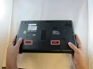
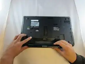
Flip device over and locate two switches on the back of the device.
-
-
-
Slide switch 1 towards the unlock symbol on the device (switch should click into place).
-
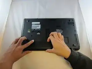
Slide switch 2 towards the unlocked symbol on the device.
-
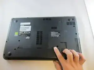
While holding switch 2 in the unlocked position, use the notch located at the top of the battery to pull battery out and away from the device.
-
-
-
Make sure that the device is unplugged, completely off, and that the device is not warm to the touch.
-
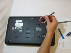
Flip the device over so you see the bottom, and loosen the 5mm PH#1 screw on the L shaped access panel.
-
-
-
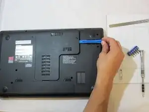
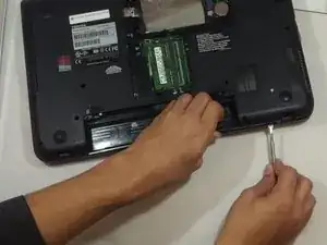
Use the plastic opening tool to open access panel by sliding it into notch near screw and prying access panel(L-shaped) away from device.
-
Pull panel completely free from device and set aside.
-
-
-
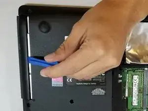
Using the plastic opening tool, pry the CD drive up.
-
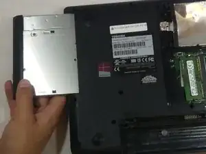
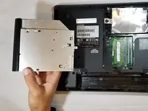
Once the CD drive is partially separated from the device, grasp with your hand and slide it out of the slot.
-
-
-
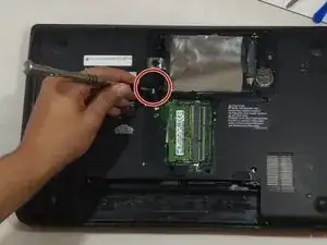
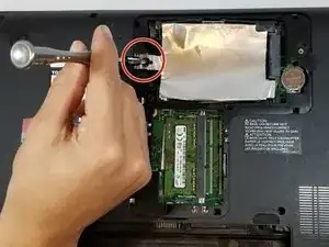
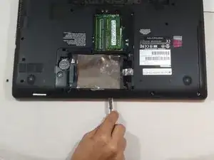
Remove the 4mm PH#1 screw on aluminum tray cover inside of access panel.
-
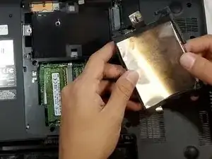
Pull aluminum cover away from device and put aside.
-
-
-
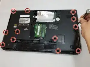
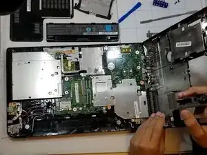
Using a metal spudger, remove the back cover by working metal spudger around edges of the laptop. Pry base away from rest of device until separated.
-
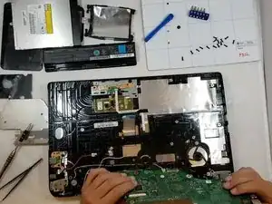
Separate back cover completely from device and set aside.
-
-
-
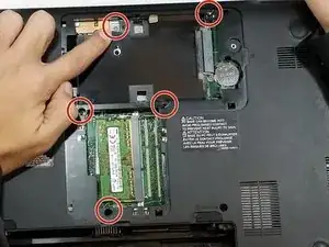
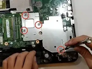
Loosen the four 5mm PH#1 screws on heat sink.
-
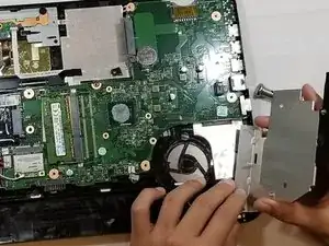
Pull heat sink out and away from motherboard and set aside.
-
-
-
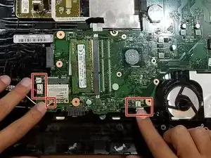
Gently unplug 5 connections on top of motherboard with your hand by applying pressure away from port while making sure not to bend any of the contacts.
-
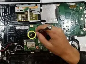
Remove the 10mm PH#1 screw securing motherboard to device.
-
-
-
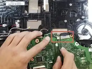
Flip motherboard over, and using the precision tweezers, disconnect the two ribbon cables.
-
Pull motherboard free from device.
-
-
-
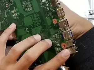
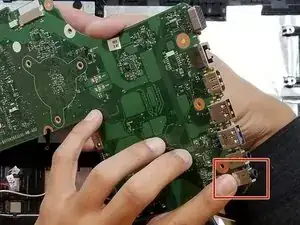
Locate headphone jack on bottom right corner of the motherboard.
-
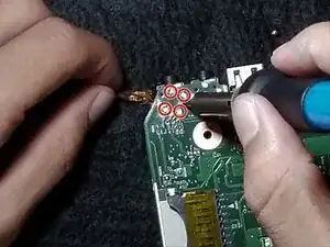
Turn motherboard over and use soldering iron and wick to melt and remove solder from 4 points holding headphone jack to the motherboard
-
Pull headphone jack from motherboard using tweezers.
-
To reassemble your device, follow these instructions in reverse order.
One comment
Whats the jack model n please? I want to buy it in advance.
