Introduction
Before attempting this guide, please have all required materials and tools. This guide is a long process and requires your full attention in order to properly replace it. When doing each step be careful and follow each step as listed.
Tools
-
-
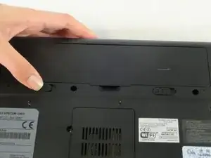
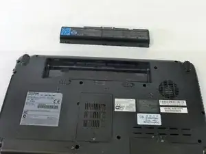
Slide the battery release tab away from the center of the laptop and hold it.
-
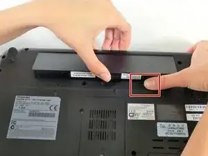
Lifting from the small notch between the two tabs, pull the battery out of the laptop.
-
-
-
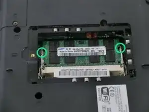
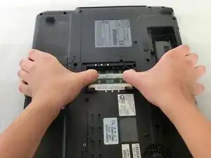
Push outwards on the metal tabs to release the RAM.
-
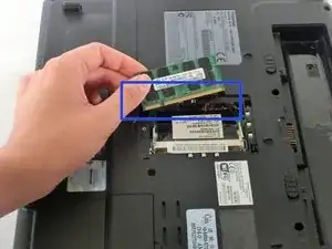
Remove the RAM. Some force may be needed.
-
-
-
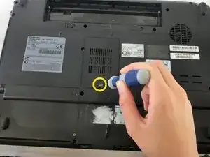
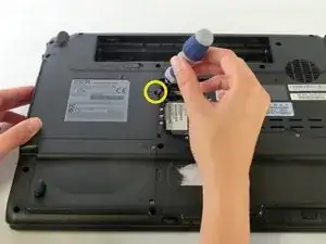
Use a PH0 screwdriver to remove the screw holding the optical drive in place.
-
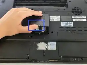
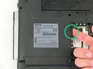
Using your index finger, push the metal tab inside the RAM bay which is located directly underneath the screw-hole.
-
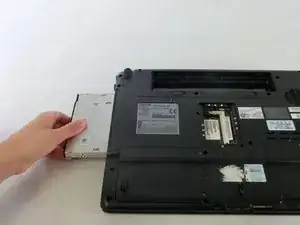
The optical drive will then slide out.
-
-
-
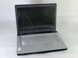
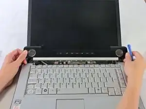
Orient the laptop so that the screen is open and facing you.
-
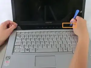
Slide the plastic opening tool underneath the top edge of the black plastic insert.
-
Pull it off and set aside.
-
-
-
Close the laptop and flip it over.
-
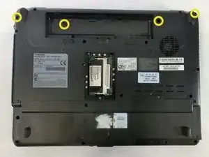
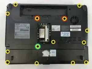
Unscrew the 11 yellow circled screws with a PH1 screwdriver. These screws are larger in size.
-
Unscrew the 2 red and yellow circled screws with a PH1 screwdriver. These screws are shorter and thicker than the previous.
-
Unscrew the 1 green and yellow circled screw with a PH1 screwdriver. This screw is longer and thinner than the previous.
-
-
-
Flip the laptop over and open it so that the screen is facing you.
-
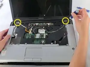
Locate the hinges on either side of the screen, which secure the display to the body of the laptop.
-
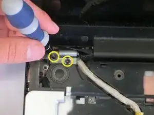
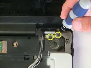
Unscrew the 2 screws in each hinge with a PH1 screwdriver.
-
-
-
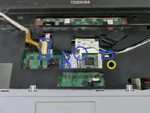
Unfasten the connectors from the highlighted locations.
-
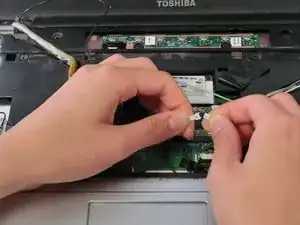
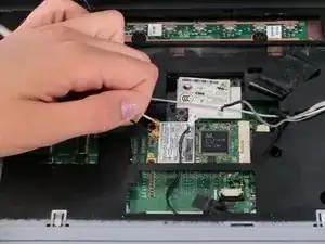
Disconnect by gently pulling on the fasteners which connect the wires to the laptop.
-
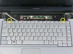
Unscrew the screw indicated by the yellow circle.
-
-
-
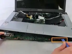
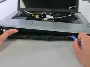
Slide the plastic opening tool underneath the edges of the upper casing, which is shown in the images.
-
-
-
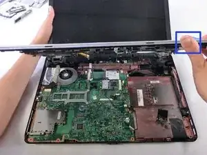
The LCD screen can now be removed from the laptop.
-
Lift the upper plastic casing and remove it from the lower half of the laptop.
-
-
-
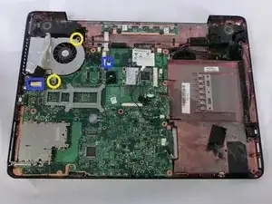
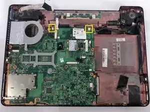
Unfasten the two connections shown.
-
Unscrew the two screws securing the fan to the laptop. Use a PH1 for the screw that is adjacent to the speaker and a PH0 for the other screw.
-
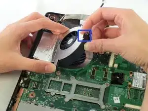
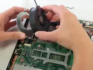
Lift up the fan and pull the black plastic tab away from the fan housing. Remove the fan.
-
-
-
First, remove the one screw with a PH1 screwdriver.
-
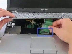
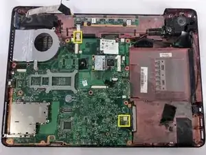
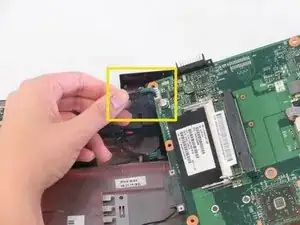
Next, remove the black connector marked by the yellow box.
-
-
-
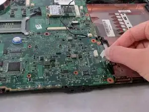
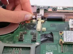
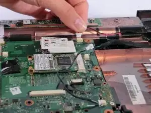
Gently pull the the small white ribbon cable from its housing on the motherboard.
-
Locate and unfasten the small white clip from the motherboard near the bottom right.
-
-
-
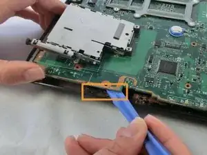
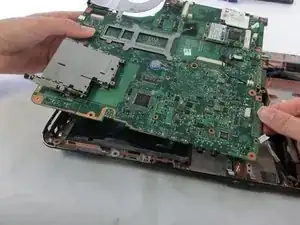
Gently slide the plastic opening tool underneath and around the motherboard.
-
Remove the connector on the underside using your fingers.
-
To reassemble your device, follow these instructions in reverse order.
