Introduction
This guide shows how to remove and replace the cylinder and cutting wedge assembly on the Toro Log Splitter 22618HD 2019 / LS-922.
For the amount of hydraulic fluid lost during this procedure, refill the hydraulic fluid tank.
-
-
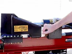
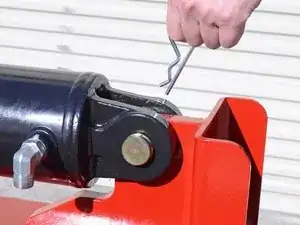
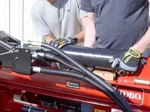
Push the control valve lever towards the rear of the device to extend the piston and advance the cutting wedge.
-
-
-
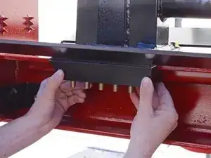
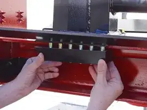
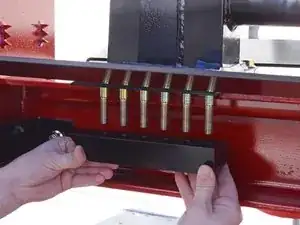
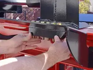
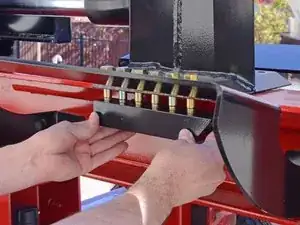
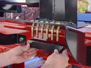
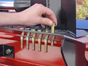
Use an impact wrench with a 3/4 inch socket to loosen the twelve bolts and twelve nuts securing the slide bars to the underside of the cutting wedge.
-
-
-
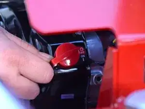
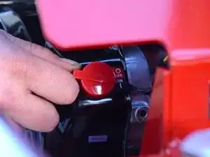
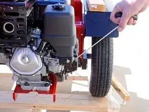
Flip the red engine ON/OFF switch to the ON position.
-
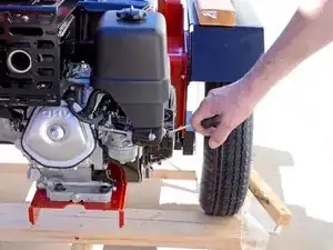
Pull the motor's pull-start cable to start the motor.
-
-
-
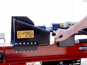
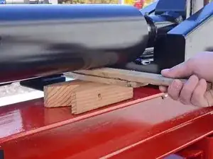
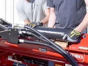
Use the control valve lever to retract the cutting wedge until it is seated underneath the dislodger bracket.
-
-
-
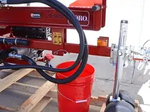
Place a bucket underneath the device, below the cylinder to catch any hydraulic fluid drips.
-
-
-
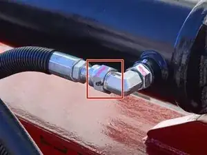
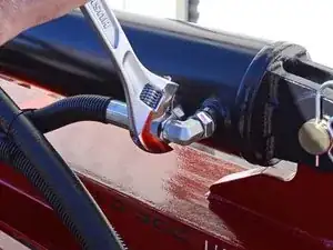
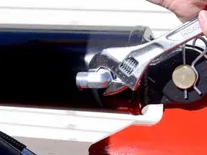
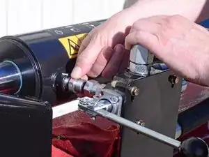
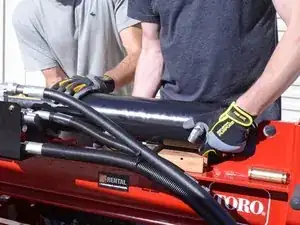
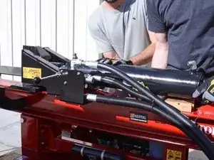
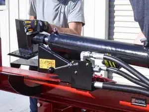
Use an adjustable wrench to loosen the nut securing the piston extension hose to the L-fitting on the side of the cylinder.
-
-
-
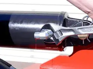
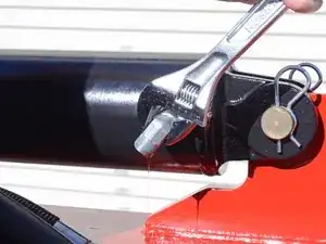
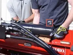
Use an adjustable wrench to loosen the nut securing the L-fitting to the side of the cylinder.
-
-
-
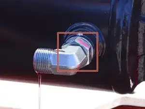
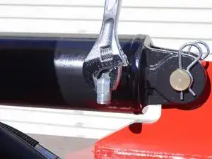
Use an adjustable wrench on the L-fitting itself to rotate it to a vertical position with the opening facing down.
-
-
-
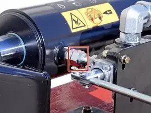
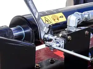
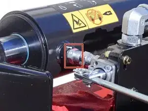
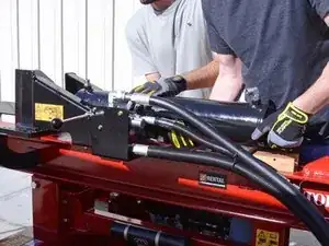
Use an adjustable wrench to loosen the nut securing the control valve to the fitting on the cylinder.
-
-
-
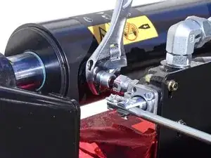
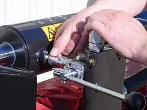
Slightly bend the control valve assembly away from the device to create a gap large enough for the fitting to clear.
-
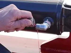
Remove the fitting.
-
-
-
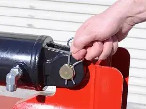
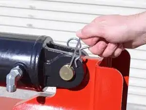
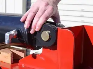
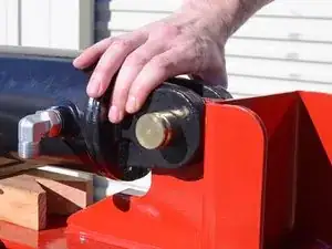
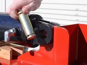
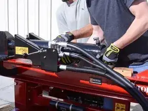
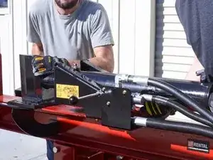
Shift the cylinder and wedge assembly towards the rear of the device, until it clears the central pin hole.
-
-
-
Support the cylinder and push the assembly towards the rear of the device until it clears the dislodger bracket.
-


To reassemble your device, follow these instructions in reverse order.
For the amount of hydraulic fluid lost during this procedure, refill the hydraulic fluid tank.