Introduction

This guide shows how to remove and replace the control valve O-rings on the Toro Log Splitter 22618HD 2019 / LS-922.

  1. Oayc2Rs5nayc1XDV
    Oayc2Rs5nayc1XDV
    g4nXlg5vKANWyicy
    • Before you begin, ensure that the engine is powered down and cool to the touch.

    • Grab the plastic housing at the end of the spark plug wire and pull firmly to disconnect it.

  2. vDPEfXkdhOkpgmJO
    vDPEfXkdhOkpgmJO
    RhSoM6jUyXRv2LPE
    • Flip the red engine ON/OFF switch to the OFF position.

  3. ZUbbVJ15Sl4HybJp
    ZUbbVJ15Sl4HybJp
    wMEtAY1n2cQoqf5Y
    • Flip the fuel valve lever to the OFF position.

  4. rVs5bIgDQNulO3Z2
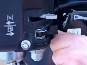
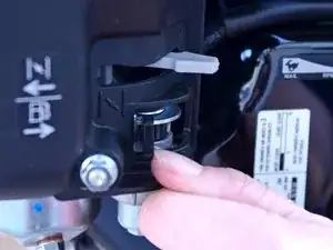
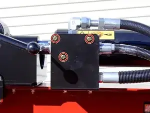
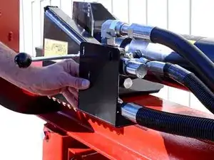
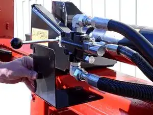
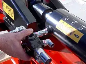
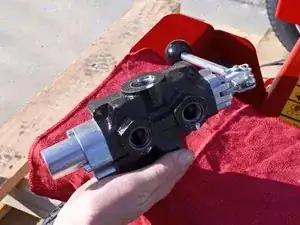
    • Use a 3/8 inch socket to remove the three bolts securing the control valve to the control valve bracket.

  5. tiuXEgvKwZUuijfs
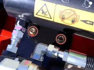
    • Use a 9/16 inch socket to remove the two bolts securing the control valve bracket to the frame.

  6. nnLTo32bqhdLmENM
    nnLTo32bqhdLmENM
    evFGBWAnfJMGd362
    • Remove the control valve bracket.

  7. bC5YhmrYTFvgfwOG
    • Residual hydraulic fluid will be trapped in the hoses connected to the control valve, and may drip during the following procedure.

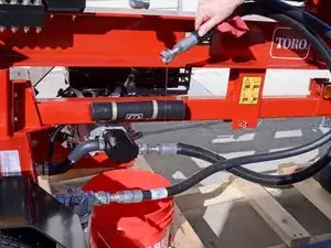
    • Place a bucket underneath the device, below the control valve to catch any hydraulic fluid drips.

    • Have rags handy to stop drips and clean up affected areas.

  8. d2EdMDlUeBc4nxYw
    d2EdMDlUeBc4nxYw
    bx4CUFgRAqcDVOZV
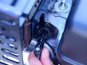
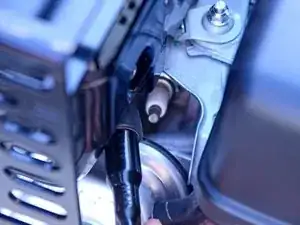
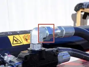
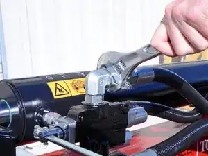
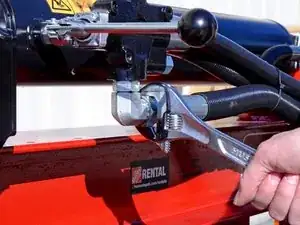
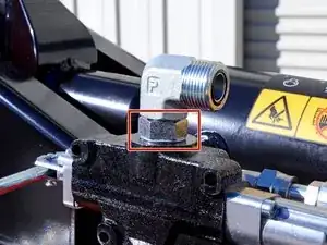
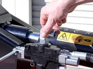
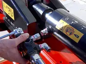
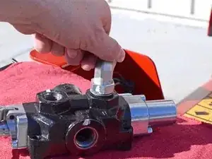
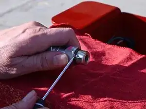
    • Use an adjustable wrench to loosen the nut securing the output hose to the L-fitting on top of the control valve.

  9. sRPBHrZyY1hAuirh
    sRPBHrZyY1hAuirh
    EHyAXxUZRxtV3ent
    • Remove the output hose from the top L-fitting.

  10. OJ3uFF23MsS1dwKl
    OJ3uFF23MsS1dwKl
    be5FF2VmIt2NPlKK
    • Use an adjustable wrench to loosen the nut holding the input hose to the L-fitting on the bottom of the control valve.

  11. MIDhtJKmAMkEK6vm
    MIDhtJKmAMkEK6vm
    1QGKvBYfjGcfUiAh
    • Remove the input hose from the bottom L-fitting.

  12. Ar4NaU3IItVCPdcK
    • Use an adjustable wrench to loosen the nut securing the top L-fitting to the control valve.

  13. bxV6CIp4XAqqykUB
    bxV6CIp4XAqqykUB
    KM3SU6dO6XxnZuym
    EJAwcm2VfQwqfc5G
    • Spin the top L-fitting counter-clockwise to remove it.

    • This fitting is part number 340-16.

  14. SqkEbDOseWVTgkUB
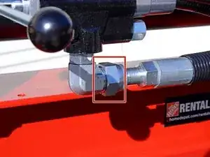
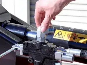
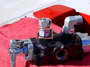
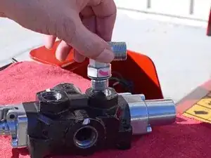
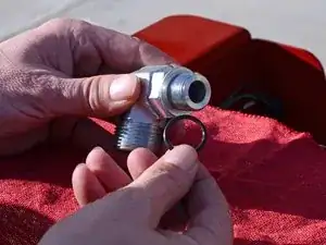
    • Use an adjustable wrench to loosen the nut securing the bottom L-fitting to the control valve.

  15. oAWgnSENFSiOkouG
    oAWgnSENFSiOkouG
    Z52PB6n4ldHPf5BJ
    ktxIFMYVClEPB6No
    • Remove the bottom L-fitting.

    • This fitting is part number 340-16.

  16. hbbLloPYWRaSKQwN
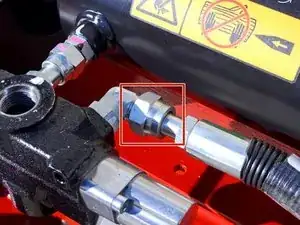
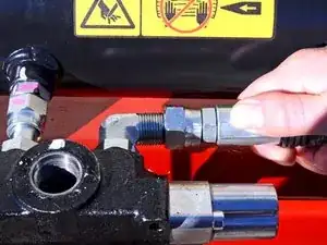
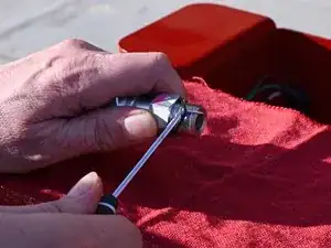
    • Use an adjustable wrench to loosen the nut securing the piston extension hose to the L-fitting on the rear of the control valve.

  17. wfPTiQKa11Ror6Vk
    wfPTiQKa11Ror6Vk
    echj6wDT6ZGTf5YS
    • Remove the piston extension hose from the rear L-fitting.

  18. dlOmZjL1G4WVAtpv
    • Use an adjustable wrench to loosen the nut securing the control valve to the cylinder.

    • This connection is the last part holding the control valve to the device, so keep the control valve supported during removal.

  19. 1eTeXNjWwpqT5DfB
    1eTeXNjWwpqT5DfB
    RHShF2SdmaGMQ2G4
    • Remove the control valve.

  20. wEvTHgcSycSKYfkB
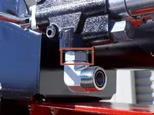
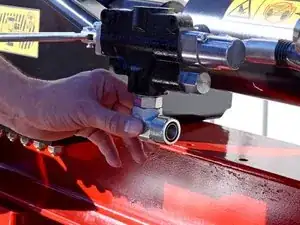
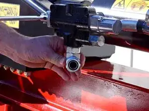
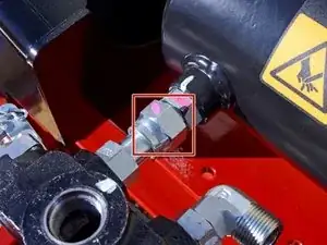
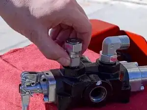
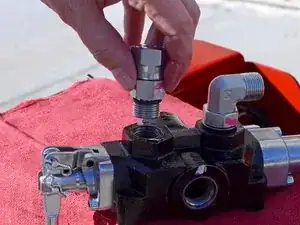
    • Use an adjustable wrench to loosen the nut securing the piston contraction fitting to the control valve.

  21. FKnsPqAFEbTe2hOd
    FKnsPqAFEbTe2hOd
    MbTuGyG1a22XHIZ6
    CN4G3fxZqbGDKO22
    • Spin the piston contraction fitting counter-clockwise to remove it.

    • This fitting is part number 100-7671.

  22. RAuQgyTYbsLkGbEJ
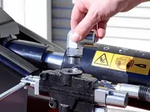
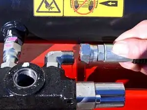
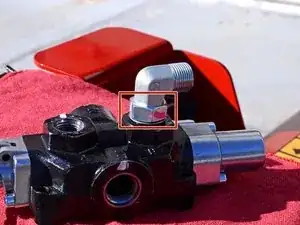
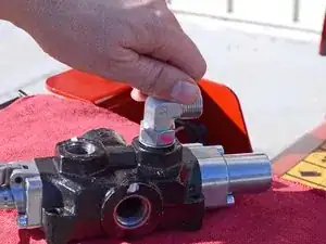
    • Use an adjustable wrench to loosen the nut securing the L-fitting to the rear of the control valve.

  23. NObgIAhShniIykOL
    NObgIAhShniIykOL
    DoROU4TFgTPqXKBP
    YA3TkxOLsfdvNfHh
    • Spin the L-fitting counter-clockwise to remove it.

    • This fitting is part number 340-98.

  24. WgQuYFTAsOEhXlBA
    • Only the control valve remains.

  25. oNkLJIuqnXRtaHBj
    oNkLJIuqnXRtaHBj
    w3hINprmFRxubfQZ
    MGnXWUDgLVAju3Rt
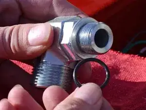
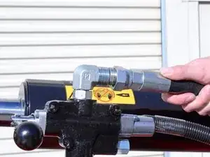
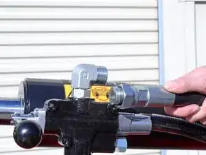
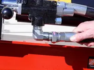
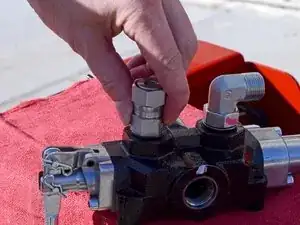
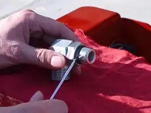
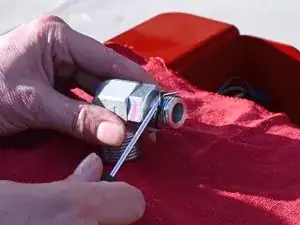
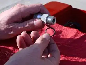
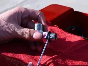
    • Use a pick tool to remove the O-ring from the output hose L-fitting, on the side that connects to the control valve.

    • This O-ring is part number 237-80.

    • The O-ring between the L-fitting and the hose is part number 237-58. Only replace this O-ring if it is visibly damaged.

  26. ZFtfmmg2cbAoZWbH
    ZFtfmmg2cbAoZWbH
    rRV41kUFQsuRpSct
    REnhuxpblermLx2w
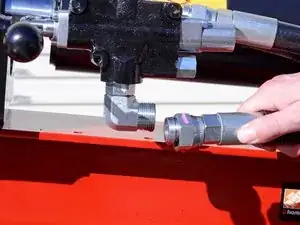
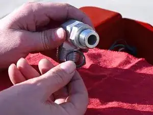
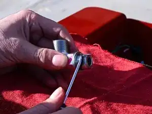
    • Use a pick tool to remove the O-ring from the input hose L-fitting, on the side that connects to the control valve.

    • This O-ring is part number 237-80.

    • The O-ring between the L-fitting and the hose is part number 237-58. Only replace this O-ring if it is visibly damaged.

  27. qlVBp25LSxXATNKO
    qlVBp25LSxXATNKO
    sNpTAqJDnR2A3SxD
    kL4sLEVMe3NJLX1k
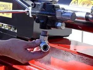
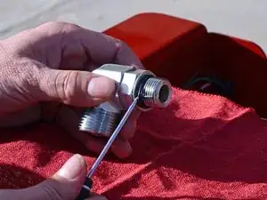
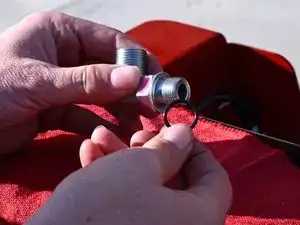
    • Use a pick tool to remove the O-ring from the cylinder contraction fitting, on the side that connects to the control valve.

    • This O-ring is part number 237-79.

    • The O-ring between the L-fitting and the hose is part number 237-30. Only replace this O-ring if it is visibly damaged.

  28. OwQroCD2GLEobAjU
    OwQroCD2GLEobAjU
    QldjLKBOdhn6AXCV
    CiPTUZr6lBURBnZy
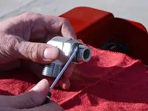
    • Use a pick tool to remove the O-ring from the cylinder extension hose L-fitting, on the side that connects to the control valve.

    • This O-ring is part number 237-79.

    • The O-ring between the L-fitting and the hose is part number 237-30. Only replace this O-ring if it is visibly damaged.

Conclusion

To reassemble your device, follow these instructions in reverse order.

Carsten Frauenheim

Member since: 10/03/20

110978 Reputation

0 comments