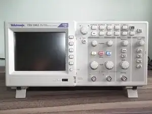
Introduction
There is a manual for this oscilloscope: TBS1000 Series Service Manual
Complete disassembly is best achieved by following the procedures in the order given in the following table:
1) Rear Feet (See page 6-8, Rear Feet.)
2) Flip Feet (See page 6-9, Flip Feet.)
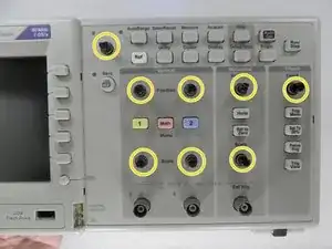
3) Front-Panel Knobs (See page 6-9, Front-Panel Knobs.)
4) Rear Case (See page 6-10, Rear Case.)
5) Front Feet (See page 6-11, Front Feet.)
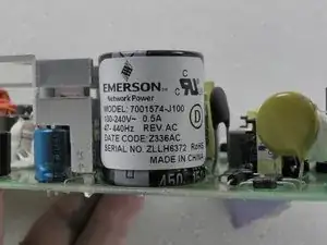
6) Power Supply Module (See page 6-12, Power Supply Module.)
7) Internal Assembly (See page 6-13, Internal Assembly.)
8) Front-Panel Cable (See page 6-15, Front-Panel Cable.)
9) Main Board Module (See page 6-16, Main Board Module (without the Display Adapter Module.)
10) Display Module (See page 6-19, Display Module.)
11) Front-Panel Module (See page 6-20, Front-Panel Module.)
12) Keypad|(See page 6-21, Keypad.)
-
-
Remove all eight plastic buttons.
-
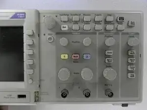
Remove the five Torx T15 screws.
-
Remove the front panel by pulling it off
-
-
-
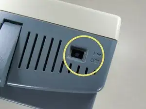
Remove the power plug from the cover
-
Firmly grasp the ON/OFF switch and pull it straight out of the box.
-
Press the button into the ON/OFF button recess until it clicks into place.
-
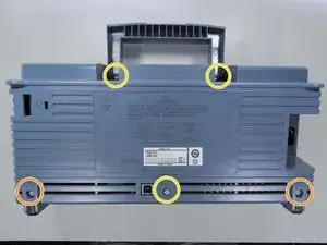
Remove the two black plastic plugs from the bottom.
-
Remove the five Torx T15 screws.
-
Remove the back cover.
-
-
-
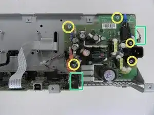
Even when disconnected, the power supply can retain a dangerously high voltage. Avoid contact with the rear of the board or other components. Use insulated electrician's gloves. Ensure that the capacitors are discharged before touching them.
-
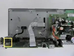
Disconnect the J101 power supply connector from the motherboard.
-
Disconnect the earth connection.
-
Remove the 5x Torx T15 screws.
-
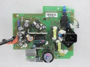
Remove the power supply board.
-
-
-
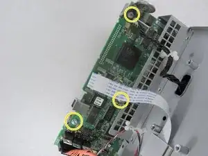
Disconnect the black cable from the motherboard
-
Remove the 5x Torx T15 screws
-
Pull the control board plate
-
-
-
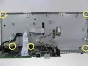
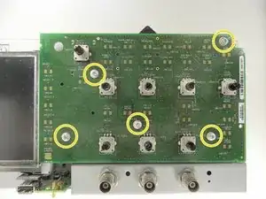
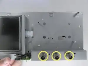
Loosen the three nuts holding the signal connectors.
-
Loosen the three T15 Torx screws.
-
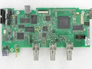
Remove the cables.
-
Remove the main board.
-
-
-
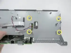
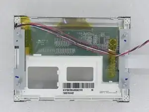
Disconnect the ribbon cable and the LCD backlight cable from the motherboard.
-
Loosen the 4x 8mm nuts from the display supports.
-
Remove the LCD display.
-
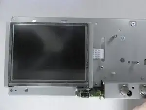
To reassemble your device, follow these instructions in reverse order.

2 comments
This guide is written in English, not Portugese. How can that be changed?
Hi Christofer.
Do you intend to translate into Portuguese? I messed up the language when editing it.