Introduction
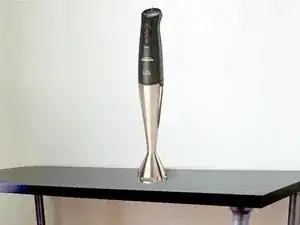
Two months after the 12 month warranty period had expired my SM8900 stick blender stopped working. It would go on occasionally for ½ second bursts after tapping it on something. This is a typical symptom of worm commutator brushes on the electric motor. This guide shows how to dismantle it and replace the worn brush.
Tools
Parts
-
-
Disconnect the stick blender from the power mains and remove any accessories from the main unit.
-
WARNING:- THE MOTOR RUNS AT ABOUT 270VOLTS DC SO BE VERY CAREFUL AND DO NOT REPAIR IT WHILE IT IS CONNECTED TO MAINS POWER. MAKE SURE IT IS UNPLUGGED FROM THE WALL.
-
-
-
1. The variable speed dial on the top popped off by putting a narrow blade knife under it and gently twisting & levering it. First position the dial to the minimum speed setting. Put a tea towel over the dial, otherwise it will come off with some speed and fly off.
-
Under the dial are two screws which attach the power cord fitting onto the unit. Unscrew these. This fitting is popped out with the same thin bladed knife. Take care to remember the position of the white variable speed gear (minimum speed setting). The power cord socket can then be gently eased off the variable speed circuit board inside the unit.
-
-
-
The lower part of the unit that holds the motor and circuit board, slides into the upper shell and is held in position by 4 lugs (90 degrees apart) about 15mm away from the external joint line.
-
As can be seen from the photos, I cut 4 slots in the housing (with a dremmel diamond blade) so as to loosen the housing and used screw drivers to force the housing off the retaining lugs. With hindsight, maybe a heat gun softening the plastic housing to just below the deformation temperature would have saved cutting the housing.
-
Once the lugs are free, the whole motor unit, including the circuit board can be pulled out of the housing. Press down the control buttons or they will jam in their rubber fittings.
-
-
-
Use a multi-meter to check for continuity across the motor terminals. Mine registered open circuit across the motor terminals so the fault was either a bad brush contact or a burnt-out armature. Luckily, it was one carbon brush that had worn right down to the metal holder.
-
Before unsoldering the circuit board from the motor, mark and photograph the position of the circuit board with the motor and also, the plastic brush holder fitting and the motor housing (otherwise it will be hard to re-assemble and the motor may spin in reverse)
-
-
-
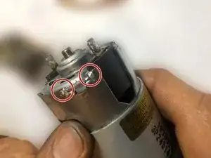
After de-soldering the circuit board from the motor, use a sharp pair of strong wire cutters to bend back the 8 lugs that are bent over the rear metal bearing housing. (These hold everything firmly in place)
-
Once the lugs are bent back a couple of large screw drivers will lever out the plastic brush holder (you can also use the knife to pry off the bearing housing prior to this to reduce force on the black plastic).
-
-
-
Inspect the carbon brushes. One was very worn down on my model, so I removed it gently with some pliers.
-
I used small files and sandpaper to make a new carbon brush from an old salvaged larger brush. Luckily the remaining brush had negligible wear and I was able to copy its dimensions (see image)
-
-
-
After some light filing the new brush popped into its holding slot and held firmly
-
Use two 2mm diameter screw drivers pushed through the holes in the plastic brush holder to hold the brushes away from each other as you push the holder back onto the motor and the brushes over the commutator
-
-
-
When re-assembling, I had to clamp together the bearing housing and motor in a vice while I tapped the 8 housing lugs back over the bearing housing.
-
Make sure that the circuit board is soldered back onto the motor terminals in exactly the same position as it was before, otherwise the control buttonswill not fit in their sockets, the motor may go backwards or the housing may not fit over the motor.
-
The motor and circuit board should now slide into the outer shell and the 4 retaining lugs should pop into their recesses.
-
Press in the power cord socket. Screw down the cord clamp and insert the variable speed gear (make sure it is at the minimum speed setting) Press on the speed dial, keeping it at the minimum speed setting. If you removed the housing without cutting it then there will be no need to seal it.
-
-
-
NOTE:- The unit uses soft-carbon commutator brushes which have a limited life. The next time I repair it, I will make the new brushes from the copper based brushes that are used in vehicle starter motors. These should last about 4 to 10 times longer than the originals.
-
To reassemble your device, follow these instructions in reverse order.


